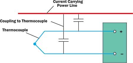
Measurements of temperature in electronic equipment and in thermal characterization apparatus are most often made with thermocouples. As with any sensor, the goal is to gather information about the environment in the vicinity of the sensor, in this case the temperature. Unfortunately the environment around the entire instrumentation chain, including the lead wires and the data acquisition system, almost always influences the measurement and its interpretation. The signal (voltage) from a typical thermocouple is low, of order 10 mV, and the signal-to-noise ratio may degrade rapidly in the presence of signal noise, inherently raising the uncertainty of the temperature measurement. One of the principle contributors to noisy thermocouple signals is the magnetic field that is generated by current carrying wires running in close proximity to the thermocouple lead wires. When a 60 Hz AC power line lies in close proximity and parallel to a thermocouple lead wire, the 60 Hz magnetic field generated by the current flowing in the power line cuts across the thermocouple pair. Capacitive coupling between the thermocouple pair and the power line, illustrated in Figure 1, induces a 60Hz “noise” voltage in the closed thermocouple circuit.The amplitude of the noise signal generated is directly proportional to the magnitude of the current in the offending power line, and inversely proportional to the distance between the thermocouple pair and the power line [1].
 |
Figure 1. Noise generation in a thermocouple circuit through coupling to a power line.
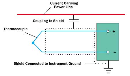
The obvious solution to the problem of course is to keep power lines a safe distance away from the thermocouple leads, and certainly not run them in a parallel configuration. But sometimes, for example when a wiring or cabling harness delivering both power and signal is snaked into electronic equipment, power lines and thermocouple lead wires are married to each other in exactly the wrong configuration for signal integrity. Fortunately, relatively simple measures can be taken to minimize the “noise.” First, one can use commercially available shielded thermocouples. Shielded thermocouples consist of a thermocouple pair surrounded by a thin metallic shroud or “shield” running along its length.As shown in Figure 2, the connector end of the shield should be connected to the ground on the voltmeter. By this method, the noise voltage is generated in the shield rather than in the thermocouple pair, and it is shorted to the system ground. A second but more expensive solution is to filter the signal.Because the signal noise is generated in a relatively narrow bandwidth around 60 Hz, a low pass filter can be used to pass the much lower frequency or DC thermocouple signal and reject or attenuate the signal components at frequencies above 60 Hz. In addition to power lines, AC motors and transformers in close proximity to the thermocouples may also induce noise voltages in the thermocouple lead wires.
 |
Figure 2. Shielded thermocouple circuit shorts noise voltage to ground, adapted from Ref 1.
In summary, common sense, shielding, and filtering as a last resort, can usually eliminate or significantly reduce signal noise in thermocouple measurements.
Reference
- Dally, J.W., Riley, W.F., and McConnell, K.G., Instrumentation for Engineering Measurements, 2nd Edition, John Wiley and Sons, NY, 1993.


