Clemens J.M. Lasance,
Guest Editor, Philips Research Emeritus, Consultant@SomelikeitCool
When Peter Rodgers invited me to again write a Thermal Facts and Fairy Tales (TF&F) column, I immediately thought of a recent webinar on basic heat sink calculations that I attended, in order to get an idea of the current status-quo in these matters. Well, in my humble view there was room for improvement. Apart from certain minor issues, I was triggered by three topics that I felt were not treated in a correct way when dealing with practical situations, namely;
- The fact that a heat sink does not only function as an area enlarger
- A much too simple explanation of the apparent (effective) emissivity of heat sinks
- The (mis)use of heat sink convective heat transfer correlations
With these three topics in mind, this TF&F column aims to outline my two cents on these issues.
- A heat sink has two functions
This topic has been treated in extenso in references [1,2], with a summary provided here. One should realize that a heat sink performs two very different functions:
- Enlarge the surface area for heat transfer
- Spread the heat (providing a significant temperature gradient exists over the dissipating surface)
Suppose we wish to calculate the effect of a heat sink attached to an arbitrary generic electronic component without modelling all component–heat sink details. The first function is easy to address: simply multiply the real-life convective heat transfer coefficient by the area enlargement factor to obtain an effective heat transfer coefficient. It is the second function that can cause a problem when we need to consider the temperature gradient over the component surface that the heat sink is to be attached to. For this analysis, let’s start by dividing the component surface into two areas: the central and periphery. When the heat sink is attached, the heat spreading reduces the maximum temperature of the central area and increases the minimum temperature in the peripheral region. This means that the effective heat transfer coefficient of the central area (required to lower its temperature is through addition of the heat sink base only) is significantly increased. Reference [1] highlights this aspect when a considerable increase in the average central heat transfer coefficient results, compared to the overall average value, i.e. 100 W/m2K versus 8 W/m2K, for a natural convection application. In this context, if we want to generate a heat sink compact model to increase the efficiency of computational fluid dynamic (CFD) models, it is therefore mandatory to always explicitly model the heat sink base, with a compact description added for the remaining fin structure. Here is a first order estimation of this effect: suppose that for certain components that exhibit a significant surface temperature gradient, the central area is one quarter of the total area, and its effective heat transfer coefficient is 12 times higher than on the peripheral area, then the influence of the base is about as strong as a three-fold total area extension.
- The question about the apparent emissivity of heat sinks
The analytical calculation of the apparent (or effective) emissivity (or emittance) of a heat sink can represent a significant effort as it depends strongly on the heat sink geometry. The apparent heat sink emissivity can be determined with high accuracy by employing radiation network theory, as discussed in pages 291-303 of reference [3]. However such calculations are no longer necessary in the age of computer-aided engineering software having embedded radiation calculation options. Let us define the heat sink geometry as shown in Figure 1(a).
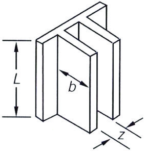
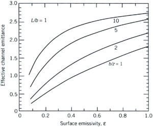
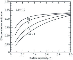
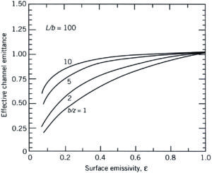
Figure 1. Effective (apparent) channel emittance (emissivity) for various heat sink geometries (taken from [3]).
The subsequent graphs shown in Figures 1b to 1d provide a realistic impression of what to expect. Herein the apparent emissivity is related to the base surface area without fins. For short and wide fins (e.g. L/b=1, b/z=1), it is obvious that a considerable part of the additional area is exposed to the environment, and hence its emissivity does matter. Furthermore, because of the extended surface area, the apparent emissivity can be greater than one because the base area is the reference. The opposite is true for long and closely-spaced fins (e.g. L/b=100, b/z=10); in this case its emissivity does not play any role, and the extended area from a radiation point of view is negligible. The point is that the radiation entering the fin channel cannot escape without multiple reflections between the fin channel surfaces. In addition, heat sinks with such a layout are only used for forced convection, hence the radiation contribution to the total heat transfer is minimal anyway. The conclusion must be: don’t bother with emissivity calculation for forced convection applications, but do for natural convection, especially for those applications where often widely-spaced fins in a non-traditional shape are used, such as in the field of light emitting diode (LED) applications.
In summary, don’t trust simple rules-of-thumb for natural convection applications. Caveat: check upfront if your application is really naturally-convection driven. In most cases you will conclude that we encounter buoyancy-induced forced convection [4]. When a heat sink has already been selected, a simple test is recommended: measure the operating temperature drop before and after painting the heat sink.
- The (mis)use of heat sink correlations
The problems with convective heat transfer correlations for practical purposes are extensively discussed in references [5-7]. Let me quote (a bit adapted) from my TF&F column of June 2015 [7].
The background in a nutshell is that the handbooks showing impressive heat transfer correlations are inherently based upon a set of conditions/constraints that are not satisfied in real-life. When you believe in the following axioms, then the “Holy Books of Heat Transfer” are consistent and comprise a wealth of information, very useful for a basic understanding of the physics. Here are the underlying axioms:
- Uniform boundary conditions, either constanttemperature or flux
- Uniform approach flow with a degree of turbulence as close as possible to zero (that’s why research type wind tunnels are huge).
- (Very) simple geometries: smooth, flat and thin plates, parallel plate channels, pipes
- Single source, especially for natural convection
- Constant properties
- Fan dynamics based on air flow chamber testing
- Extended surfaces based on Murray-Gardner assumptions (see e.g. [8])
- “Complex shapes” means there exist an analytical solution
- Heat spreading limited to one-layer, one-sided heat transfer
- Radiation diffuse and grey
This means that if and only if the physical situation conforms to the assumptions does the experimenter have the right to assume that the predicted results will be obtained. That means much more than simply matching Nusselt (Nu) with Rayleigh (Ra) or Reynolds (Re) numbers. Specifically, most analytical (and numerical) studies assume uniform flow velocity with a specified turbulence (often zero), uniform temperature and the origins of the velocity boundary layer and the thermal boundary layer on the surface. For many fields of heat transfer, such as turbulence, boiling, heat exchangers, channel flow, etc., these axioms form a sound base. Not so for electronics cooling at the system level.
Especially when referring to heat sinks, the author published a TF&F column titled “How useful are heat sink correlations” in [9]. Bottom line is that to use correlations to obtain a reasonable estimation of heat sink performance is a fairy tale. What’s wrong is that most equations are based on the following assumptions, in addition to the ones previously listed:
- Parallel plate heat sinks
- Fully ducted flow
- Fully developed flow
- Strong impact of 3D flow (especially in natural convection) not considered
- Equal number of fins and channels
- Negligible entrance and exit effects
- Laminar and uniform approach flow
- No temperature gradient in heat sink base
- Heat spreading effect of base not taken into account
- Uniform fin temperature (both between fins and within a fin)
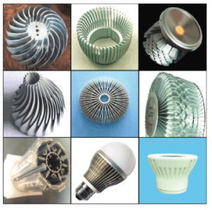
Now, have a look at some state-of-the-art heat sink geometries for LED applications in Figure 2, in addition to the ones pictured in the December 2013 TF&F column [9].
Is there anyone out there who can tell me with a straight face that a Nusselt number correlation based on parallel-plate heat sinks will predict a realistic performance of these products? I don’t think so.
Obviously, if you use handbook equations to base your heat sink design upon, or to predict the performance of a selected heat sink type, chances are high that you may miss all of the heat sinks shown in Figure 2. Sure, extrusion-based parallel-plate heat sinks are the cheapest around, but they score badly when it comes to optimization of shape, weight, volume, and performance, especially regarding optimal fin thickness. And the final argument in favor of using CFD codes instead of correlations: 3D printing is a booming business, and for sure parallel plates are not the ones that will be high on the list for optimization.
Conclusion
The starting point for this column was my experience with a heat sink webinar. I was not happy with the approach that it was presented, and the reasons why have been outlined in this column.
To all who want to transfer basic heat sink knowledge: tell facts, not fairytales. The fact is that reality is complex. Basic heat transfer about conduction, convection and radiation: OK, but tell the attendees also that in order to realize a competitive edge in eventual sales, much more knowledge is needed than some limited and outdated design rules. Compare it with electronic design: nobody believes that one is capable of designing a functional printed circuit board (PCB) after attending a webinar of half an hour. After this column one should understand why it is not simple to assess heat sink performance, which should be the bottom line.
References
[1]Lasance, C.J.M., “The Influence of Various Common Assumptions on the Boundary-Condition-Independence of Compact Thermal Models,” IEEE Transactions on Components and Packaging Technologies, Vol. 27, Issue 3, pp. 523 – 529 (2004).
[2]Lasance, C.J.M ., “Heat Sink Basics from an Industrial Point of View,” Chapter 9 in: Thermal Management of LED Applications: Volume 2 – Solid State Lighting Technology and Application, Lasance C.J.M. and Poppe A. (Eds), Springer, New York, USA, pp. 347-387 (2014).
[3]Kraus, A. and Bar-Cohen, A., Design and Analysis of Heat Sinks, Second Edition, John Wiley and Sons, New York, USA, pp. 291-303 (1997).
[4]Moffat, R.J. and Ortega, A., “Buoyancy Induced Forced Convection,” Heat Transfer in Electronic Equipment, ASME, New York, US, HTD-Vol. 57, pp. 135-144 (1986).
[5]Lasance, C.J.M., “Sense and Nonsense of Heat Transfer Correlations Applied to Electronics Cooling,” in Proceedings of the Sixth Conference on Thermal, Mechanical and Multiphysics Simulation and Experiments in Micro-Electronics and Micro-Systems (EuroSimE), Berlin, Germany, April 18-20, pp 8-16 (2005).
[6]Lasance, C.J.M., “Most of Us Live neither in Wind Tunnels nor in the World of Nusselt,” ElectronicsCooling, June 2010, https://electronics-cooling.com/2010/04/thermal-facts-and-fairy-tales-most-of-us-live-neither-in-wind-tunnels-nor-in-the-world-of-nusselt/, accessed August 5, 2016.
[7]Lasance, C.J.M, “The Holy Books of Heat Transfer: Facts or Fairy Tales?” ElectronicsCooling, June 2015, https://electronics-cooling.com/2015/05/the-holy-books-of-heat-transfer-facts-or-fairy-tales/, accessed August 5, 2016.
[8]Kraus, A., Aziz, A., and Welty, J., Extended Surface Heat Transfer, A Willey-Interscience Publication, John Wiley and Sons, New York, USA (2001).
[9]Lasance, C.J.M., “How Useful are Heat Sink Correlations for Design Purposes?” ElectronicsCooling, December 2013, https://electronics-cooling.com/2013/12/heat-sink-correlations-design/, accessed August 5, 2016.
Contact Information
Clemens J.M. Lasance
Consultant
SomelikeitCool
Nuenen, the Netherlands
Email: lasance@onsnet.nu


