Introduction
Most Electronics Packaging Engineers and Analysis Specialists have access toa wide range of high quality analysis tools. While a few computer programs useanalytical methods, the majority are based on numerical analysis techniques.Although these programs are becoming easier to use, they typically requireconsiderable skill, and they are certainly capable of producing results with ahigh order of accuracy. However, even with these elegant tools at his/herdisposal, the Design Engineer should have a working knowledge of lesssophisticated methods.1 A first order analysis may, for example,predict temperatures sufficiently high so as to indicate that further designconsideration is more necessary than in-depth thermal analysis. Additionally,many engineers work in small companies that cannot afford sophisticated analysistools. Although these smaller companies have the option of hiring a consultantto perform the most complex calculations, it is in the interest of theresponsible design engineer to perform a first order analysis in order toascertain the magnitude of the thermal design problem.2 An exampleof a first-order analysis of a fan cooled enclosure is the subject of thefollowing paragraphs.
The Problem
The fan-cooled enclosure shown in Figure 1 is used to illustrate the method.The forward portion of the bottom panel is slotted (about 50% open) to providean inlet grill. The internal geometry consists of five circuit board channelsand a power supply. The power supply is totally sealed with the exception ofthe front and rear panels, each of which is perforated in a manner that providesabout 35% open area for airflow. It shall be assumed that the power supply isapproximately 50% filled with typical electronic components on a 0.025 m pitch.
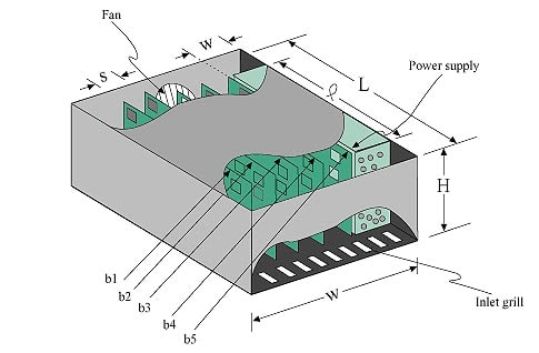 |
s = | circuit board spacing = 0.025 m. |
| w = | power supply width = 0.075 m. | |
| l = | power supply and circuit board length = 0.250m. | |
| L = | enclosure length = 0.300 m. | |
| W = | enclosure width = 0.200 m. | |
| H = | enclosure height = 0.125 m. | |
| QPS = | power supply dissipation = 25 W. | |
| Qi = | heat dissipation for circuit board bi= 20, 20, 20, 20, 30W; i=1…5. | |
| Figure 1: Forced air cooledenclosure with five circuit board channels and a power supply. | ||
The five circuit boards are on 0.025 m centers and a single fan on the rearpanel negatively pressurizes the enclosure. A simple, non-flow restricting,wire grill is placed over the external fan face.
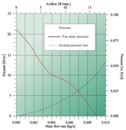
The fan characteristics are illustrated in Figure 2 as fan static pressurevs. mass flow rate. Such a curve is required for a system analysis and isusually obtained from the fan manufacturer’s product catalog. The dashed curveindicated as system pressure loss will be discussed later, but it should bementioned here that one of the desired results of any system analysis is todetermine the system operating point as indicated by the intersection of the fanstatic pressure and system pressure loss curves.
The Model and Analysis
The typical first-order system analysis of a forced-air cooled enclosureuses a circuit representation where pressures (relative to the external ambient)may be calculated at node points and air flow may be calculated in resistiveelements, (see [1] for additional detail). It should be clear that the accuracyof this method is dependent on the ability of the analyst to:
(1) correctly determine the location of the elements and also
(2) to calculate the element values.
Admittedly, such modeling may be somewhat subjective, but with a littlecare, the analyst will usually obtain quite reasonable results, particularly inview of the fact that little effort is required to perform such an analysis. Furthermore, most people have access to some form of network solver such as anelectronic circuit analyzer, a modest thermal network analyzer or even amathematical “scratch pad” program. These computerized networkmethods are very useful for parametric analysis and sensitivity studies, thus providing considerable insight into the relative importance of the various flowand thermal phenomena in the problem.
A suggested circuit for the present problem is shown in Figure 3. The fivecircuit board channels are represented by air flow resistances R1-R5;the inlet grill by resistance R6; the power supply inlet, internalmembers, and exit by resistances R7, R8, and R9,respectively. The resistance of the wire finger guard at the fan exit isignored. Since each card channel is presumed to have the same geometry, e.g.card spacing and component height, the five circuit boards could also have beenmodeled as a single card cage represented by a single resistor. In the presentcase, the card cage was subdivided into five elements primarily to illustratethat non-identical card channels may also be modeled.
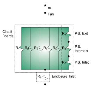 |
Figure 3: Airflow/pressurecircuit for fan-cooled enclosure |
The flow resistances for this problem were selected from [1], although thereare more specialized texts that the reader may find useful [2]. The relevantformulae are listed in table cellspacing=”0″ A1 and the actual calculation of each resistance isshown in table cellspacing=”0″ 1.3 A noteworthy feature of all of the resistancesis the inverse-square dependence on a cross-sectional area. In the case of theinlet grill and the power supply inlet and exit panels, the relevant area is thefree-cross-sectional area within the plane of the element, i.e. the actual areathrough which the air flows.
table cellspacing=”0″ A1: Some formulae for calculating airflowresistances at sea level altitude and modest average temperatures.
Perforatedor slotted plate:
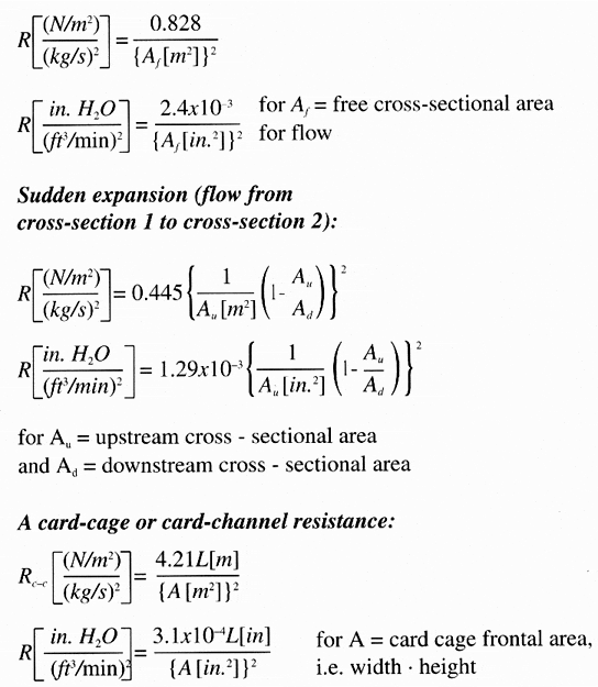
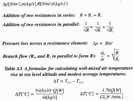
table cellspacing=”0″ A2. Formulae for combining and using airflow resistances.
| RPS | = R7 + R8 + R9 |
| = 7.70×10⁴ + 3.76×10⁵ + 7.70×10⁴ | |
| = 5.30×10⁵ (N/m2)/(kg/s)2 |
The reader will note that in table cellspacing=”0″ 1, the internal components of the powersupply have been approximated by a series addition of 10 (pitch = 0.250 m/0.025m = 10), 50% slotted panels.
The five circuit board channels are combined in parallel to form a singleresistance RCB:


Rsys = R6 + R1 =1.28×10⁵ + 3.60×103 = 1.32×10⁵ (N/m2)/(kg/s)2
The system loss pressure is finally computed from
psys = Rsysm2
and plotted as shown in Figure 2.
The total system airflow is determined by the intersection of the fan staticpressure and the system loss pressure curves. Reference to Figure 2 shows thatthe total system flow is therefore m = 0.0069 kg/s. The variousbranch flows are:

Conclusions Concerning the Sample Problem
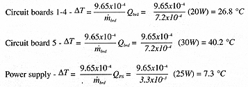
Most electronic equipment designers would consider the calculated well-mixedair temperature rises to be too large. Furthermore, it would not be surprisingto expect temperature hot-spots considerably greater than the values calculated.Individual component surface temperatures could also be estimated using anappropriate heat transfer coefficient and the component power dissipation (thisproblem would be best treated in a separate discussion).
Clearly, the design needs to be re-evaluated in terms of a more appropriatefan or perhaps even more fans. The designer should also check with theelectronic engineers on the project to ascertain if the provided heatdissipation values are indeed realistic. It is not uncommon for initialestimates to be of a worst case nature that may never actually occur.
Footnote:
- Application of first order methods is also recommended forproblems such as conduction solutions using fixed temperature orconvection/radiation boundary conditions. In addition, a first order method mayoften be used to determine a boundary condition value for input into a finiteelement or finite difference program.
- The reader is cautioned that a first order analysis maynot have sufficient resolution to permit detection of all problem areas.
- The author has provided formulae and performed theanalysis in SI units, which are not yet in full usage in the US. Fan vendorliterature still indicates some confusion as to what should be consideredstandard with regard to presentation of fan static pressure and fan airflow. The reader will note that fully consistent with SI units, the fan and systempressures are computed in the SI units of N/m2 and the fan air flowin kg/s.
- An assumption of turbulence is not necessary forderivation of rules for adding resistors, although the rules may depend on thenature of the assumed flow. The square root sign used for addition of parallelflow resistors follows directly from the turbulent model represented by
p = Rm2
References
1. Ellison, Gordon N., Thermal Computations forElectronic Equipment, Robert E. Krieger Publishing Co., Malabar, Florida, 1989.
2. Fried, Erwin and Idelchik, I.E., Flow Resistance: A Design Guide forEngineers, Hemisphere Publishing Corporation, New York.

