Introduction
The importance and utility of air filters is often underestimated since itis typically an after-thought in the design cycle. The wrong filter is oftenused for an application which may compromise the electrical and thermalperformance of the system as a result of contaminant build-up. In this article,different filter designs and the selection process is reviewed to assist thedesign engineers in selecting a suitable cellspacing=”0″ filter for their specific application.
Filter Purpose
The three main reasons air filters are used in forced convection coolingsystems are:
- To remove particulate contaminants from the air
- To create a laminar air flow
- To attenuate electromagnetic interference (EMI).
Particulate Contaminants
The importance of the removal of corrosive materials is well appreciated,but the reason for removing more benign ones (dust and dirt) may not be asobvious. These particles can accumulate on and in between electronic components,resulting in an electrical short and shrouding. The latter can alter air flowdistribution and thus adversely affect thermal performance.
The particles removed by air filters range from normal indoor dust and lintto corrosive elements such as solvents, humidity and salt. The size of theparticles depends upon the material. Dust and bacteria particles are 50 micronsin diameter and tobacco smoke is about 0.5 microns. The removal of particles isobviously a function of their diameter and larger ones are easier to remove.
Laminar Air Flow
Flows with less turbulence are better in many applications because theyhave less friction and subsequently require less fan work. The latter is verydesirable since fan generated acoustic noise is a point of contention in theforced convection cooling of electronic systems.
Electromagnetic Interference
Some electronic components are susceptible to electromagnetic interference,which can cause a malfunction (giving distorted signals), or a break down. Mounting electronics in a metallic enclosure would provide adequate protectionagainst EMI, if it were not for the openings created to allow air to flow forcooling. Therefore, metallic ventilating barriers are coupled with air filtersto attenuate electromagnetic signals.
Operating Characteristics
There are a variety of materials used as filter media. These include coarseglass fibers, metallic wools, expanded metals and synthetic open cell foams. Each type of filter medium will have its own filter efficiency and pressure dropat a given air flow.
Filter Efficiency
Filter efficiency is the percentage measure of the air borne particulatesthat a filter is able to remove from the flow at a given velocity. Some of thestandards and their definitions are shown in table cellspacing=”0″ 1. Hence, filters withhigher efficiency have a larger pressure drop for a given air velocity. Also,the smaller the particle a filter can collect, the greater the pressure dropacross the filter for a given air velocity.
| table cellspacing=”0″ 1. | |
| ASHRAE STD 52-76 synthetic dust weight arrestance | Measures the weight of test dust retained by the filter as a percentage ofthe total weight of dust used. |
| ASHRAE dust spot efficiency | Compares the discoloration effect of filtered air containing normal dirtparticles with that of non-filtered air. |
| MIL-STD-282 DOP | Measures the percentage of Di-Octyl Phthalate smoke retained by the filter. The particle tested is 0.3 microns. |
Pressure Drop
Filter pressure drop is a measure of the force required to move air throughthe filter at a given velocity. Each component in the system contributes aresistance to the air flow, which results in a pressure drop across itself. Thetotal system resistance is the sum of all the pressure drops along the air flowpath (including the filter).
The air filter pressure drop is a function of the velocity of the air andthe filter type (medium). Each filter medium will have a unique pressure versusair velocity characteristics. Performance curves showing these characteristicsare used by designers during the filter selection process.
Filter Selection
Several specifications are required before an appropriate filter can beselected. A minimum list of specifications would be:
- The available area for the filter.
- The system’s volumetric flow rate.
- The maximum pressure drop allowed for the filter.
- Agency specifications (UL, CSA…)
- Filter efficiency
- Type of contaminants to be filtered
- a). size of particles
- b). corrosive or non-corrosive
The choice of filter types is then limited to those which meet the list ofspecifications.
A suggested procedure is to first narrow the field of possible choices tothose which meet the application’s agency, efficiency and contaminant removalrequirements. For example, an application may require the filter to removesolvents and meet UL (Underwriter’s Laboratory) specifications for flammabilityresistance. Therefore, filters meeting those specifications could be used(aluminum or coarse glass fiber would be appropriate).
Second, choose the filters which meet the pressure drop requirement of theapplication. Performance curves are used to determine the pressure drop across afilter for a given air velocity.
Air velocity through a filter can be calculated using:
| V = | R/A | (1) |
| where | ||
| V = | velocity | |
| R = | volumetric flow rate (ft3/min) | |
| A = | filter planar area. |
It would not be appropriate to select a filter with a pressure drop equal tothe maximum allowed by the system. Such a filter would have a short operatinglife. Due to the fact that as soon as the filter started to collect particles,the pressure drop would increase beyond the allowed maximum.
A good rule of thumb is to select a filter that has 1/2 or less than themaximum pressure drop allowed by the application. For example, if the blowercan deliver the required flow rate at 1.5 in H2O (3.8 cm H2O),and the system itself will have a pressure drop of 1 in H2O (2.54 cmH2O) at that air flow, then the maximum allowable pressure drop forthe filter would be 0.5 in H2O (1.25 cm H20). Therefore, the selected filtershould have a pressure drop of 0.25 in H2O (0.63 cm H2O)or less.
If a filter cannot be found that meets the allowable pressure drop for theapplication, then a redesign of the system is required. Either the pressuredrop across the filter has to be reduced or a blower capable of meeting thepressure drop would have to be selected.
If it is necessary to reduce the pressure drop across a filter for a givenR, then the filter area has to be increased. This may be accomplished byincreasing the actual space available for the filter, and/or pleating the filtermedium. The increase in filter area will decrease the air velocity through thefilter (Eqn 1). This in turn decreases the pressure drop across the filter.
Example:
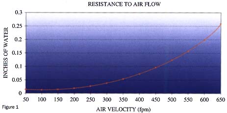
A designer calculates the required volumetric flow rate of air to be 300 ft3/min(1.52 m/s), and the maximum allowable filter pressure drop to be 0.1in H2O(0.254 cm H2O). The filter medium chosen is a 2 inch (5 cm) thickaluminum mesh with the desired filter area 0.59 ft2 (548 cm2).Figure (1) shows the performance curve for this filter.

For this system to work properly the filter pressure drop will have to be1/2 or less than the maximum filter pressure drop allowed by the system (0.05 inH2O, 0.13 cm H2O). Therefore, the pressure drop must becalculated from the air flow. Referring to Eqn (1), the air velocity is givenby:
V = R/A = (300 ft3/min)/0.59 ft2 = 508 ft/min (2.58m/s)
The performance curve shows that the filter pressure drop for a velocity of508 ft/min is 0.12 in H2O (0.31 cm H2O). This isgreater than the maximum pressure drop desired for the filter.
Therefore, a more powerful blower needs to be used or the filter area has tobe increased. It is generally more practical to increase the filter size ratherthan use a higher capacity blower, due to the associated cost of higher capacityblowers.
Before the appropriate filter area can be calculated, the air velocity whichresults in the proper pressure drop must be determined. This can beaccomplished by using the filter performance curve. Once the velocity isdetermined Eqn (1) can be used to calculate the filter area.
The filter performance curve shows that the air velocity for 0.05 in H2O(0.13 cm H2O) should be 325ft/min (1.65 m/s). By rearranging Eqn(2), the proper filter area can be found as follows:
A = R/V = (300 ft3/min)/(325 ft/min) = 0.92 ft2(854.7 cm2)
This new filter area can be accomplished by increasing the height of theoriginal desired filter area by 3 inches (7.5 cm2) approximately.
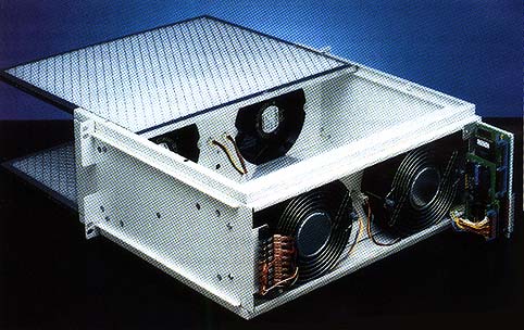
Selection of a filter to create laminar air flow is straight forward. Choose a filter medium that has a uniform porosity, such as a non-wovenpolyester filter. Even more important than the filter selection is theorientation of the filter with respect to the fan or blower. The filter shouldbe placed several inches away from the blower or fans via a mixing plenum. Thefilter should also be oriented perpendicular to the desired air flow direction,Figure (2).

In many applications, metallic barriers are used in conjunction with airfilters to reduce electromagnetic interference. Although these barriers do notremove contaminants from the air, they are combined with filters often enough tobe discussed here.
There are four choices of metallic barriers available for use with filtersfor EMI protection. They are as follows:
- Perforated sheet
- Random mesh of round fibers
- Square mesh of round wire
- Waveguide-beyond-cutoff
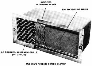
| The most applicable choice for forced convection cooling is thewaveguide-beyond-cutoff, otherwise known as a honeycomb mesh, Figure (3). Thisis because of its low pressure drop at high air velocities. The name “waveguide-beyond-cutoff” comes from the fact that EMI frequencies higher than the “cutoff”frequency are guided to the metallic enclosure holding the filter assembly. These EMI frequencies are then grounded by the enclosure. Frequencies less thanthe cutoff are attenuated so that they are not disruptive to the electronicequipment in the enclosure. The cutoff frequency and the attenuation values aredetermined by the dimensions of the cells making up the honeycomb, specificallythe length and width. Here, a cell is one hexagonal tube within the honeycombmesh, (cells can come in other shapes, e.g. square). The equations relating thecutoff frequency and attenuation level to these cell dimensions for an idealwaveguide are as follows: |  Figure 3: A standard packaged blower from McLean Engineering showing a honeycomb mesh usedfor EMI protection. |
Attenuation = 27.3 x Length Width, dB (2)
Width = (1.5 x 10¹⁰)/Cutoff frequency, cm (3)
Attenuation levels are usually around 100dB for adequate EMI protection.
Designers therefore can use Eqn (2) and (3) to determine the cell size basedon the EMI specifications of the application.
Summary
It is easy to see why there may be a compromise to the cooling applicationif the filter is not included as part of the design process. The benefits offilter use can only be assured by understanding why they are used and knowingthe correct selection procedure.
References
1. Thomas C. Ottney, Determining Filter Requirementscan be a Challenge, assn. responds, Air Conditioning , Heating &Refrigeration News, April 24, 1995.
2. Thomas C. Ottney, Air Filter Efficiency, Air Conditioning, Heating &Refrigeration News, October 14, 1991.
3. An Accelerator Pedal for Cooling Fans, Reprint from Machine Design,September 26, 1994.
4. Air Filtration Components, Chapter II of the 1991 version of the HVACSystems Applications Manual, Air Conditioning, Heating & Refrigeration News,October 14, 1991.


