Introduction
Since the development of the first electronic computers in the 1940s, thedevelopment of faster and denser circuit technologies and packages has beenaccompanied by increasing heat fluxes at the chip and package levels. Over theyears, significant advances have been made in the application of air coolingtechniques to manage increased heat fluxes. Although air cooling continues to bethe most widely used method for cooling electronic packages, it has long beenrecognized that significantly higher heat fluxes can be accommodated through theuse of liquid cooling. Application of liquid cooling for microelectronics may becategorized as either indirect or direct.
Indirect liquid cooling is one in which the liquid does not contact themicroelectronic chips, nor the substrate upon which the chips are mounted. Insuch cases a good thermal conduction path is provided from the microelectronicheat sources to a liquid cooled cold-plate attached to the module surface, asshown in Figure 1. Since there is no contact with the electronics, water can beused as the liquid coolant, taking advantage of its superior thermophysicalproperties.
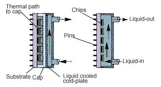 Figure 1: Example of indirect and directliquid immersion cooling for a multi-chip module package.
Direct liquid cooling, the focus of this article, may also be termed directliquid immersion cooling, since there are no physical walls separating themicroelectronic chips and the surface of the substrate from the liquid coolant.This form of cooling offers the opportunity to remove heat directly from thechip(s) with no intervening thermal conduction resistance, other than thatbetween the device heat sources and the chip surfaces in contact with theliquid. Interest in direct liquid immersion as a method for cooling integratedcircuit chips may be traced back as early as the 1960s.
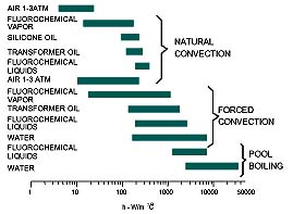
Direct liquid immersion cooling offers a high heat transfer coefficientwhich reduces the temperature rise of the chip surface above the liquid coolanttemperature. As shown in Figure 2, the relative magnitude of a heat transfercoefficient is affected by both the coolant and the mode of convective heattransfer (i.e. natural convection, forced convection, or boiling). Water is themost effective coolant and the boiling mode offers the highest heat transfercoefficient. Direct liquid immersion cooling also offers greater uniformity ofchip temperatures than is provided by air cooling.
Coolant Considerations
The selection of a liquid for direct immersion cooling cannot be made on thebasis of heat transfer characteristics alone. Chemical compatibility of thecoolant with the chips and other packaging materials exposed to the liquid mustbe a primary consideration.
There may be several coolants which can provide adequate cooling, but only afew will be chemically compatible. Water is an example of a liquid which hasvery desirable heat transfer characteristics, but which is generally unsuitablefor direct immersion cooling on account of its chemical characteristics.Fluorocarbon liquids (e.g. FC-72, FC-86, FC-77, etc.) are generally consideredto be the most suitable liquids for direct immersion cooling, in spite of theirpoorer thermo-physical properties.
As shown in Table 1, the thermal conductivity, specific heat, and heat ofvaporization of fluorocarbon coolants are lower than water [1]. These coolantsare clear, colorless per-fluorinated liquids with a relatively high density andlow viscosity. They also exhibit a high dielectric strength and a high volumeresistivity. The boiling points for the commercially available “Fluorinert”liquids manufactured by the 3M Company, range from 30 to 253 °C.
| PROPERTY | FC-87 | FC-72 | FC-77 | H2O |
| Boiling Point @ 1 Atm (°C) | 30 | 56 | 97 | 100 |
| Density x 10-3 (kg/m3) | 1.633 | 1.680 | 1.780 | 0.997 |
| Specific Heat x 10-3 (w-s/kg-K) | 1.088 | 1.088 | 1.172 | 4.179 |
| Thermal Conductivity (w/m-K) | 0.0551 | 0.0545 | 0.057 | 0.613 |
| Dynamic Viscosity x104 (kg/m-s) | 4.20 | 4.50 | 4.50 | 8.55 |
| Heat of Vaporization x10L-4 (w-s/kg) | 8.79 | 8.79 | 8.37 | 243.8 |
| Surface Tension x103 (N/m) | 8.90 | 8.50 | 8.00 | 58.9 |
| Thermal Coefficient of Expansion x 103 (K-1) | 1.60 | 1.60 | 1.40 | 0.20 |
| Dielectric Constant | 1.71 | 1.72 | 1.75 | 78.0 |
Table 1. Comparison of thermophysicalproperties of some fluorocarbon coolants and water
These liquids should not be confused with the “Freon” coolantswhich are chlorofluorocarbons (CFCs). Although some of the “Freons”(e.g. R-113) exhibit similar cooling characteristics, concern over theirenvironmental effect on the ozone layer preclude their use.
Modes of Heat Transfer
The convective heat transfer processes upon which liquid immersion coolingdepends may be classified as natural convection, forced convection, or boilingmodes. The relative magnitude of heat fluxes which can be accommodated by eachmode is shown in Figure 3, as a function of “wall superheat” orsurface-to-liquid temperature difference for a typical fluorocarbon coolant.
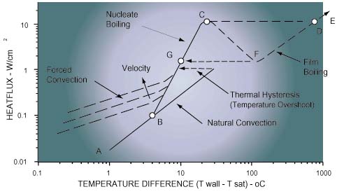
Natural Convection: As in the case of air cooling, naturalconvection is a heat transfer process in which mixing and fluid motion isinduced by coolant density differences caused by the heat transferred to thecoolant. As depicted in Figure 3, this mode of heat transfer offers the lowestheat flux or cooling capability for a given “wall superheat”. Nonetheless, the heat transfer rates attainable with liquid natural convectioncan easily match or exceed those attainable with forced convection of air.Natural convection would typically be employed within a closed container totransfer heat from chips or modules to liquid, and then from the liquid to thewalls of the container. Heat could then be transferred from the walls to outsideair by natural or forced convection.
Forced Convection: Higher heat transfer rates may be attained byutilizing a pump to provide forced circulation of the liquid coolant over thechip or module surfaces. This process is termed forced convection; and as withair cooling, the allowable heat flux for a given surface-to-liquid temperaturedifference can be increased by increasing the velocity of the liquid over theheated surface. Depending upon the surface geometry and the nature of the flow(i.e. laminar or turbulent), the heat transfer coefficient will be proportionalto the velocity to a power between 0.5 and 0.8. The price to be paid for increasing cooling performance in this way, will be a higher pressure drop. This can mean a larger pump and higher system operating pressures. Althoughforced convection requires the use of a pump and the associated piping, itoffers the opportunity to remove heat from high power modules in a confinedspace; and then transport the heat via the liquid coolant to a remote heatexchanger to reject the heat to air or water.
Boiling: Boiling is a complex convective heat transfer processdepending upon liquid-to-vapor phase change by the formation of vapor bubblesat the heated surface. It is commonly characterized as either pool boiling(occurring in a stagnant liquid) or flow boiling. The pool boiling heat transferrate usually follows a relationship of the form,
Q = C’sf A (Twall – Tsat)n
where Q = C’sf is a constant depending on each fluid-surfacecombination, A is the heat transfer surface area, Twall is thetemperature of the heated surface, and Tsat is the saturationtemperature (i.e. boiling point) of the liquid. The value of the exponent n istypically about 3.
The boiling curve for a particular surface and fluid of interest (e.g.silicon and FC-72) is usually obtained experimentally. An example of a boilingcurve depicting the cooling path from natural convection to film boiling isshown in Figure 3. If chip power is gradually increased in small steps, coolingoccurs first by natural convection (A – B). Eventually a power level is reachedat which sufficient superheat is available to initiate the growth of vaporbubbles on the surface and boiling starts (B). As power is increased, morenucleation sites become active and the frequency of bubble departure increases.The region between B and C is termed the nucleate boiling regime. Vigorousagitation of the hot boundary along the heated surface, and gross fluidcirculation caused by the motion of the vapor bubbles, provide the ability toaccommodate substantial increases in heat flux with minimal increases in surfacetemperature. As power is increased to point C, the critical heat flux conditionis reached. So many bubbles are generated at this point that they begin to forma vapor blanket inhibiting fresh liquid from reaching the surface. Furtherincreases in power will result in a transition to film boiling (D – E). In thisregime heat transfer from the surface to the liquid is dependent on thermalconduction through the vapor and it is very poor. In most electronic coolingapplications, transition to film boiling will result in failure due to hightemperatures. To take advantage of boiling to cool electronic devices, it isdesirable to operate in the nucleate boiling regime (B – C).
A problem often associated with pool boiling of fluorocarbon liquids is thatof temperature overshoot. This behavior is characterized by a delay in theinception of nucleate boiling (i.e. beyond point B), such that the heatedsurface continues to be cooled by natural convection; with increased surfacetemperatures unless a sufficient superheat is reached for boiling to occur. Thisbehavior is a result of the good wetting characteristics of the fluorocarbonliquids and the smooth nature of silicon chips. Although much work [2] has beendone in this area, it is still a potential problem which the Thermal Engineermust consider. There is usually little or no temperature overshoot associatedwith flow boiling cooling applications.
The typical critical heat fluxes encountered in saturated (i.e. liquidtemperature ‘ saturation temperature) pool boiling of fluorocarbon liquidsranges from about 10 to 15 w/cm2, depending upon the nature of thesurface (i.e. material, finish, geometry). The allowable critical heat flux maybe extended by subcooling the liquid below its saturation temperature. Forexample, experiments conducted at IBM demonstrated that it is possible toincrease the critical heat flux to as much as 25 w/cm2 by droppingthe liquid temperature to -25 °C.
Higher critical heat fluxes may be achieved using flow boiling. For example,heat fluxes from 25 to over 30 w/cm2 have been reported for liquidvelocities of 0.5 to 2.5 m/s over the heated surface [3]. Heat fluxes in excessof 100 w/cm2 have been obtained with a FC-72 liquid jet impingingupon a 6.5 mm x 6.5 mm chip at a flow rate of 2.2 cm3/s [4].
Application Examples
In spite of prolonged interest in direct immersion liquid cooling as a meansto cool high heat flux micro-electronics, there have been only a limited numberof applications. As with indirect liquid cooling, these applications have beenalmost exclusively in the large mainframe and supercomputer arena. This is notsurprising, since this has been the microelectronics technology sector with thehighest packaging densities and concentration of heat.
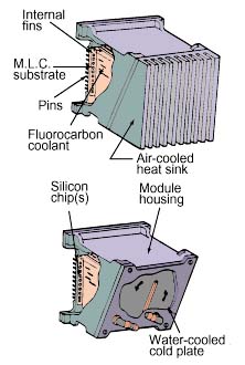
The Liquid Encapsulated Module (LEM) developed at IBM in the 1970s providesan example of a package utilizing pool boiling. As shown in Figure 4, asubstrate with integrated circuit chips (100) was mounted within a sealedmodule-cooling assembly containing a fluorocarbon coolant (FC-72). Boiling atthe exposed chip surfaces provided high heat transfer coefficients (1700 to 5700w/m2-K) to meet chip cooling requirements. Internal fins provided ameans to condense the vapors and remove heat from the liquid. Either anair-cooled or water cooled cold-plate could be used to cool the module. Usingthis approach, it was possible to cool 4 W chips (4.6 mm x 4.6 mm) and modulepowers up to 300 W. Direct liquid immersion cooling has been used within IBMfor over 20 years, as a means to cool high powered chips on multi-chipsubstrates during electrical testing prior to final module assembly.
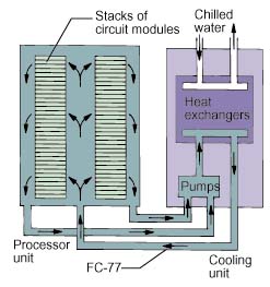
An example of a large scale forced convection fluorocarbon cooling system isprovided by the CRAY-2 supercomputer [5]. As shown schematically in Figure 5,stacks of electronic module assemblies were cooled by a forced flow of FC-77 inparallel across each module assembly. Each module assembly consisted of 8printed circuit boards on which were mounted arrays of single chip carriers. Atotal flow rate of 70 gpm was used to cool 14 stacks containing 24 moduleassemblies each. The power dissipated by a module assembly was reported to be600 to 700 watts. Coolant was supplied to the electronics frame by two separateframes containing the required pumps and water-cooled heat exchangers to rejectthe total system heat load to customer supplied chilled water.
Other Considerations
Although this discussion has concentrated on the merits of immersioncooling, coolant selection, and possible modes of heat transfer; several otherconsiderations should be kept in mind when considering direct liquid immersionfor cooling electronics. Since fluorocarbon liquids are expensive they shouldonly be considered for use in closed systems. Whether the application is in aself-contained module like the LEM or a forced flow scheme, care must be takento ensure that the seal materials chosen are compatible with the liquid.Information or guidance in this regard may sometimes be obtained from themanufacturer of the coolant. If boiling is to take place, then the design mustincorporate a means to condense the resulting vapors. A finned surface may bedesigned for this purpose as in the LEM example, or a remote finned condensersurface cooled by air or water might be used. In flow systems, care must betaken in selecting a pump. The relatively high vapor pressure of the low boilingpoint fluorocarbons generally require that a higher suction head be provided toprevent cavitation in the pump. Whether using a self-contained boiling module ora circulating flow system, care should be taken to make sure all internalsurfaces in contact with the coolant are clean. This will ensure thatmanufacturing process residues or unclean surfaces do not introduce acontaminant into the liquid which could be carried to the heated chip surfacesand interfere with the boiling process. In forced circulating liquid systems, itmay be desirable to add a particulate and a chemical filter to ensure thelong-term purity of the coolant. By selecting the appropriate liquid coolant andthe mode of heat transfer, and by giving appropriate attention to these otherconsiderations; direct liquid immersion cooling can be used successfully toprovide an effective solution for cooling high heat flux chips and packages.
Robert E. Simons
Electronics Cooling Applications,
16Shamrock Circle, Poughkeepsie, NY 12603 USA
Tel: +1 (914) 471 8893 Fax:+1 (914) 471 8893
Email: bob.simons@bbs.mhv.net
References
1. Danielson, R.D., Tousignant, L., and Bar-Cohen, A.,Saturated Pool Boiling Characteristics of Commercially Available PerfluorinatedLiquids, Proc. of ASME/JSME Thermal Engineering Joint Conference, 1987.
2. Bergles, A.E., and Bar-Cohen, A., Immersion Cooling of DigitalComputers, Cooling of Electronic Systems , Kakac, S., Yuncu, H., and Hijikata,K., eds, Kluwer Academic Publishers, Boston, MA, pp. 539-621, 1994.
3. Mudawar, I., and Maddox, D.E., Critical Heat Flux in Subcooled FlowBoiling of Fluorocarbon Liquid on a Simulated Chip in a Vertical RectangularChannel, Intl. J Heat and Mass Transfer, 32, 1989.
4. Chrysler, G.M., Chu, R.C., and Simons, R.E., Jet Impingement Boiling ofa Dielectric Coolant in Narrow Gaps, IEEE Trans. CHMT-Part A, Vol. 18 (3), pp.527-533, 1995.
5. Danielson, R.D., Krajewski, N., and Brost, J., Cooling a SuperfastComputer, Electronic Packaging and Production, pp. 44-45, July 1986.


