Introduction
After selecting or designing a heat sink based upon a given air velocity orvolumetric flow rate through the fins, the thermal designer needs to determinethe total amount of flow which must be delivered in the duct or card passagecontaining the module w with heat sink. As shown in Figure 1, some of the flowwill go around or bypass the heat sink. In fact, depending upon the free area onthe sides and above the heat sink in comparison to the flow area between thefins, a significant portion of the approaching air flow will simply bypass theheat sink. Although computational fluid dynamics codes offer a very useful toolfor analyzing flow through and around the heat sink, the methodology describedhere provides a simple technique for obtaining an initial estimate of flowbypass for use in air moving device selection and trade-off studies. Thisapproach is an extension of that originally described by Lee [1].


Considering the geometry shown in Figure 2 and applying the condition of amomentum balance across the control surfaces (1 and 2) we obtain:
and
where Vd is the velocity in the duct approaching the heat sink,Vf is the velocity in the fin passages, and Vb is thevelocity in the bypass region. Assuming the pressure drop in the bypass region,Pb, to benegligible compared to the pressure drop,
Pf, in the finpassages, we combine equations 1 and 2 to obtain:
Applying the condition of a mass balance across the control surfaces, wefurther obtain:
AdFd=
AbVb+
VfAf
where, Ad is the duct cross-sectional area, Ab isthe flow bypass area, and Af is the flow area between the fins.Taking into account Ahs, the frontal area of the heat sink, we have:
Ad = Ahs + Af + Ab
Equation 4 may now be used to find the air velocity in the bypass regionsurrounding the heat sink:
Squaring the bypass velocity we obtain:
which may be substituted for Vb2 in equation (3),
Rearranging terms in equation (8) results in,
which is a quadratic equation of the form,
AVd2 + bVd + c = 0
with,
The velocity in the duct required to achieve velocity Vfbetween the fins is then:
and the total required volumetric flow rate, Gd is
Gd = Ad Vd
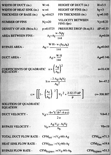
Each of the areas required to calculate the numerical values of thequadratic coefficients may be determined readily from the geometry of the ductand heat sink. The value of velocity Vf is determined from a heatsink analysis or vendor data as that which is required to achieve the desiredheat sink thermal resistance. The heat sink pressure drop (including entranceand exit effects), Pf, at velocity Vf , is determined byanalysis, experimentally, or using vendor data. This flow bypass analysis maybe easily automated using a spreadsheet or similar calculation tool and providesa useful tool at the early stages of a thermal design project. An example ofthe analysis in the form of a Mathcad file is shown in Table 1.
Table 1 – Example of Mathcad file for heatsink air flow bypass analysis.
References
1. Lee, S., Optimum Design and Selection of Heat Sinks,IEEE Trans., CPMT-A, Vol. 18, No. 4, Dec. 1995.


