Introduction
Dark light, deafening silence, cruel kindness, living dead, fuzzy logic,honest politics. The adjectives seem to contradict the substantives; such afigure of speech is called an oxymoron. It will be argued within this articlethat ‘thermal resistance’ is also a serious candidate for this category, atleast if the concept is being applied without realizing the differences betweenthermal and electrical resistances, rather the rule than the exception inpractice.
The notion of ‘thermal resistance’ is deeply rooted in the vocabulary of thethermal designer. Every textbook treats the fundamental analogy betweenelectrical and thermal resistance, and all the thermal data found in theComponent Data Sheets is presented in the form of either thermal resistance fromjunction to case (Rth j-c) or junction-to-ambient (Rth j-a).Usually, these resistances are defined somewhere in the introduction. Ofcourse, it is possible to define everything, and to call it what you want, aslong as the expressions at both sides of the equal sign have the samedimensions. There is no law that the definition should make sense froma physical point of view. Nobody objects to the use of the phrase ‘dark light’in a poem. And here we meet the problem. Most people are of the opinion thatthe definition should have a physical significance, on the grounds that anelectrical resistance certainly has a physical meaning (the voltage between twopoints divided by the current from one point to the other), and smart professorstold them that electrical and thermal differential equations are identical.
Electrical and thermal resistances
Unfortunately, the conclusion ‘electrical and thermal resistance areanalogous’ is wrong, while the proposition ‘electrical and thermal differentialequations are analogous’ is right. Why? Mother Nature has to be blamed.Somehow, at the beginning of time (or maybe even before that), the buildingstones of matter and life were arranged in such a way that what an electricalengineer calls ‘insulation’ is about 20 orders of magnitude away from what hecalls ‘conduction’, while, in thermal terms, the difference between ‘insulation’and ‘conduction’ is about 3 orders of magnitude. To highlight the distinction,the thermal difference between insulation and conduction is about the differencein conduction between high-doped and low-doped Silicon in electrical terms (Ref.1). Maybe better so; just imagine how the world would look, if it was the otherway around.
This mere fact has a very important consequence which,regrettably, is often not mentioned by the same professors who usually focusonly on the mere elegance of the symmetry in the differential equations:
in many cases of practical importance, there is no suchthing as purely one-dimensional heat conduction in the thermal world, incontrast to the electrical world.
Let us recall the definition of electrical resistance:
“The voltage difference between two points divided by the currentthat flows between them is the electrical resistance.”
This definition is so simple because it is usually applied to single wires,tracks or blocks in which all the streamlines leaving the first node end at thesecond node. Now, let us try to define thermal resistance in the same sense.It turns out that the definition should be very carefully formulated, to arriveat a precise and unambiguous meaning. We propose the definition as provided inref. 2.
“The temperature difference between isothermal surfaces divided bythe heat that flows between them is the thermal resistance of the materialsenclosed between the two isothermal surfaces and the heat flux tube originatingand ending on the boundaries of these two isothermal surfaces.”
Many of the apparent paradoxes presented in the literature on this subjectare attributed to the application and measurement of thermal resistances tosituations in which their physical meaning, according to the above definition,is not well defined. For example, take the thermal resistance of some package,from junction to case. In practical circumstances, this resistance cannot be aninvariant quantity designated by one number, because the orientation of internalconduction heat flow paths changes in response to changes in the thermalenvironment. In other words, this thermal resistance is no longer a function ofthe package parameters, but becomes dependent on the boundary conditions. Interms of the definition, it means simply that the location of the heat flux tubeis not constant. Part of the heat leaving the junction and entering the casemight take a completely different path, see the second example below.
The JEDEC standard
The recently-issued JEDEC Standard (’95) also recognizes the fact that thetemperature difference between two points divided by the power dissipated is nota thermal resistance. The standard introduces a new quantity, viz. thejunction-to-top-center-of-package thermal characterization parameter, denoted byJC, definedas the temperature difference between junction and top center of the packagedivided by the power. The top-to-ambient thermal characterization parameter isdenoted
TA.Although the junction-to-ambient thermal resistance is the sum of the twoparameters
JCand
TAneither of these components individually is a thermal resistance: “Thethermal characterization parameters,
JC and
TA, have theunits of K/W, but are mathematical constructs rather than thermal resistancesbecause not all of the heating power flows through the exposed case surfaces.”
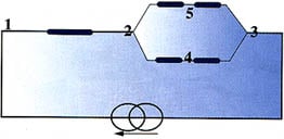
To probe this issue further, consider the following example. We split anelectrical wire, and measure the voltage across points 1 and 4 according to thefollowing sketched scheme:
Now, we ask an electrical engineer what the resistance is between thesepoints. Probably he or she will cordially suggest a consultation with a shrink,and yet, this happens frequently in the thermal world.
For example, call node 1 ‘junction’, node 2 ‘die attach’, node 3 ‘ambient’,node 4 ‘central-case’, and node 5 ‘outer-case’. Suppose the temperaturedifference between ‘central-case’ and ‘junction’ is measured, and divided bysome power (usually the total dissipation). It is common practice to call theresult the ‘junction-to-case thermal resistance’. Obviously, there is noanalogy here between electrical and thermal resistance, for the simple reasonthat an electrical resistance does not exist between the two points mentioned.
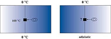
Let us take another example to illustrate the failure of the concept ofthermal resistance. Consider an infinite strip of plastic with adiabatic sides,with a width to thickness ratio of 4, and an electrical wire running through thecenter which can be heated. Suppose we impose a constant temperature of 0 °Cat both remaining sides (‘bottom’ and ‘top’). Let the dissipation be such thatthe temperature of the wire is 100 °C. If one is asked to draw theequivalent resistor network, it will obviously look like the figure on the left:
It turns out that this is a physically correct formulation, because it is aconsequence of the formal definition cited before. Let us replace the constanttemperature boundary condition at the bottom with an adiabatic boundarycondition (the previous figure on the right). The question is: what will be thenew temperature? Based on the network representation, the answer followsimmediately: 200 °C, because obviously the heat flux through the bottomresistor is zero, and the effective heat transfer area halves. What is the realanswer? About 120 °C! The first answer is not even close. The reason is,as noted before, that the heat transfer paths change completely as a result ofthe change in boundary conditions, and, consequentially, the network derived forthe first situation cannot be used for the second one.
Figure 1. Iso-flux lines for a 2d isotropic bar.Left figure: top and bottom constant temperature, sideadiabatic. Right figure: top constant temperature, bottom and side adiabatic.
The problem
The problem comes down to the following:
In some cases, thermal resistances could be derived that make sense. Incloser examination, the chances are high that the thermal behavior can bedescribed by approximately 1D heat conduction. In other cases (likej-c), thedefinition clearly violates the physics, at least, if one is of the opinion thatthe term ‘resistance’ should resemble the meaning in the electrical field. Theresulting value, though, might have practical relevance. For many plasticpackages, a network can be derived for a certain application. The network mayconsist of two resistances (for example, junction-to-board andjunction-to-case), or more. Using the same network for other boundaryconditions could result in large errors, as demonstrated in many paperspublished by the DELPHI consortium (Ref. 3). To overcome this problem, thevalues of the network resistors can be fitted by optimization techniques toaccommodate many different boundary conditions. However, in doing so, theresulting ‘thermal resistances’ lose their physical meaning completely, asargued in Ref. 4, and one may wonder if the term ‘thermal resistance’ should bekept, on account of the persistence of the analogy in the minds of mostscientists and designers for some time to come.
Conclusion
In summary, the conclusion that should be drawn from the preceding sectioncan be formulated as follows:
In all cases, a thermal resistance can be defined, but in many practicalcases, the physical significance of the definition is meaningless, with theexception of those definitions which incorporate the ultimate heat sink (anambient at uniform temperature) as one of the nodes.As a consequence, thewidespread notion of a universal analogy between electrical and thermalresistances hampers a correct understanding of the physics.”
In closing, the author feels strongly that understanding the way in whichthermal resistances differ from their electrical counterparts might help thedesigner in correctly interpreting his or her thermal resistance measurementsand calculations.References
1. de Mey, “Misunderstandings of Heat Transfer in theElectronics Engineering Community”, Proce. THERMINIC, 1995, Villard deLans, France.
2. Rosten and C. Lasance, “DELPHI: The Developmentof Libraries of Thermal Models of Electronic Components for an Integrated DesignEnvironment”, in Model Generation in Electric Design, eds. J. Berge et al.,Kluwer, 1995, pp. 63-90.
3. Rosten, H., “Final Report to SEMITHERM XIII on theEuropean-Funded Project DELPHI: The Development of Libraries of Thermal Modelsof Electronic Components for an Integrated Design Environment”, Proc.SEMITHERM XIII, Austin TX, 1997, pp. 73-91.
4. Lasance C., “Thermal Characterization ofElectronic Parts with Compact Models: Interpreation, Application, and the Needfor a Paradigm Shift”, Proc. SEMITHERM XIII, Austin TX, 1997, pp. 40-48.


