Telephone equipment has traditionally been housed in large buildings, sheds and outdoor cabinets. The cooling of these facilities has been carried out using traditional methods. However, in many of the new systems being developed and deployed such as broadband ISDN, cellular and/or cable, heat dissipation densities will increase substantially [1].
Furthermore, the introduction of the electronics into outside plants has imposed serious constraints on enclosure design since temperature and humidity are the two major causes of electronics failure in the telecommunications industry. To meet the demands of protecting equipment in the outdoor environment, the industry has been pushing for sealed designs that allow for little or no exchange of cabinet air with the outside air [2].
Outdoors, it is not only necessary to remove the heat generated by the electronics, but also the effects of the solar loading. The effects of solar loading can be substantial, depending upon the size of the enclosure and its orientation towards the sun (see [3, 4, 5, 6, and 7] for more details on thermal management issues).
Another important design issue is cooling device selection and its impact on power, battery backup and maintenance. Fully active systems, which like air conditioners require AC power, are nearly impossible to back-up efficiently and, in addition, require high levels of maintenance [8, 9]. Assisted systems, such as air-to-air heat exchangers, which run off DC power, can be backed up with longer maintenance intervals. On the other hand, passive systems require no power and are maintenance free. The choice of thermal management systems, therefore, requires a balance/trade-off between heat load and cost.
Small enclosures are a challenge because the heat they receive as solar radiation accounts for half or more of the total cooling load, although this situation is changing rapidly as designers install more and more equipment in these enclosures. What is a small enclosure? The definition is not easy to give. However, a good rule-of-thumb is to consider as small, any enclosure that needs to be cooled by assisted means such as air conditioners, air-to-air heat exchangers, thermoelectric coolers, etc.. Phase Change Materials (PCMs) are a relatively new concept for electronic enclosures (see [8] and [9] for previous examples). A PCM is used to absorb peak energy loads during one time of the day and then to reject that heat load at another time. PCM materials typically have high heats of fusion (energy absorption required to change the PCM from a solid to liquid), which allows small volumes of material to absorb/store large amounts of energy when it undergoes a phase change. The addition of a PCM to an enclosure can prevent the use of assisted systems or fully active systems to maintain the electronics at the desired conditions. With a PCM, the melting point is selected such that the energy from the electronics is absorbed while it undergoes phase change or melts. It can then be solidified (recharged) once the ambient temperature goes below its melting point.
The issues regarding the proper design of outdoor cabinet thermal management systems have been dealt with in detail in the literature [3, 4]. The present article discusses the numerical simulation of the cabinets using Phase Change Materials (PCMs) before prototyping in order to: a) provide preliminary information on the thermal constraints upon the system, b) and, more importantly, to ascertain the efficacy of the cabinet’s thermal management system and to determine the improvements that must be made.
Using PCMs in Electronic Enclosures
All types of outdoor equipment can be cooled using PCMs. Most designers like to use passive methods on account of their simplicity and lack of maintenance. Passive methods rely primarily on natural (free) convection in conjunction with PCMs and solar reflectors. Natural convection is the transport of heat by buoyancy-induced fluid flows.
PCMs are substances that change phase, most often from solid to liquid, as they absorb heat. PCMs are selected for the temperature at which they change phase and for the latent heat associated with phase change. PCMs are sometimes used in conjunction with thermosiphons. Typical PCMs for high temperature applications include waxes, salts and paraffins. Water (ice) is used for low temperature applications.
 |
 |
|
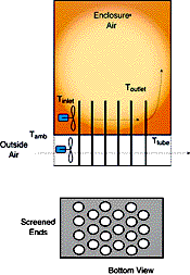
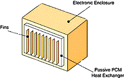
| Figure 1 – Schematic of assisted heat exchanger that relies on PCMs. | Figure 2 – Schematic of a passively-cooled electronic enclosure. The passive PCM heat exchanger, only shown on one surface, can be placed on as many surfaces as needed. |
The PCM is kept inside or attached to the enclosure in appropriately designed and sealed reservoirs (see Figure 1 and 2). PCMs takes advantage of thermal inertia and phase change effects. For example, an enclosure with PCMs during daylight hours will absorb heat through the cabinet walls and protect the electronics within the enclosure from overheating. The heat absorbed during the day will then be released to the outside world at night when it is cooler.
PCMs can also be incorporated into assisted systems for the cooling of enclosures. In order to enhance cooling, PCMs can be incorporated into a heat exchanger structure in which two fluids that are at different temperatures are separated by a PCM (possibly in encapsulated form). Hotter, internal air is first circulated through the heat exchanger and cooled by transferring its energy to the PCM, which slowly changes phase. This will occur during the hottest part of the day when external air temperatures prevent the use of outside air to cool the enclosure. Later in the day, when outside air temperatures drop, outside air is brought in to remove the heat stored in the PCM. Figure 1 shows a sketch for this simplified heat exchanger.
The PCM material, used to absorb energy to prevent the enclosure from overheating in the summer, also functions as thermal mass during the winter in order to retain as much generated heat as possible. It should be noted that various types of enclosure, will require various types of PCMs and designs that take into consideration internal temperature and external/internal heat load conditions.
Design Issues for Using PCMs
There are three general classes of PCM that can be used effectively for a PCM heat exchanger [10]. These three classes are salt-hydrates, paraffins, and non-paraffin organics. The three most important factors to consider in the selection of a PCM are:
- the cost of PCM
- the safety, toxicity and environmental characteristics of the PCM
- the useful life of the PCM
The thermal properties of salt-hydrates can deteriorate as a result of undergoing thermal cycling. The impact of the cycling can be decreased through the addition of additives to the salt-hydrates and by mechanical agitation or mixing. Glauber’s salt (sodium sulphate, 10-hydrate) is a very popular PCM material, but it may not be adequate for those applications requiring a high number of thermal cycles, unless properly encapsulated. Data obtained from material safety data sheets (MSDSs) indicates that it is not a significant health hazard. In addition, the cost for Glauber’s salt is low.
The use of paraffins or other organic materials is also possible and may be advantageous because the phase change temperature can be selected over a wide range (0 to 120°C). Review of MSDSs for candidate materials also indicate that paraffins pose no significant health or safety hazards. Rather than use a single pure chemical species, the actual paraffin or organic can be a mixture of hydrocarbons. The phase change for these mixtures will occur over a small temperature range.
Thermal Design Issues
When designing a passive PCM heat exchanger there are several issues that must be addressed. These include:
- heat absorption during the day
- solar load and reflector design
- heat rejection during off peak times
- stress levels within the reservoir
The amount of energy that is to be absorbed during the day directly determines the volume of PCM that must be used in the heat exchanger. The energy absorbed depends on the total thermal load and the energy generated by the electronics within the enclosure. To determine the design load, a simple steady-state analysis can be performed of the complete system to determine how much heat can be rejected for a specified internal temperature. The difference between the heat rejected and the total thermal load (electronics and solar) then determines the maximum thermal load the PCM must be able to absorb.
Another factor that influences the calculation of the PCM volume is the number of thermal cycles the system will experience over its useful life, before there is degradation of the thermal properties. Knowledge of the degradation then leads to the application of a safety factor in the calculation of the PCM volume.
The melting of the phase change material in the reservoir or tubes depends on many factors:
Heat Absorption = f (Tmelting, Twall, T, t, H, PCM Thermal Properties, havg, Tube wall thermal Properties, etc).
The process is transient and the rate of heat absorption (and melting of the material) is not uniform.
The melting of the PCM is typically a lesser issue than the resolidification of the PCM. The driving force to melt the PCM is the difference between the phase change temperature of the PCM and the enclosure air temperature. This temperature differential is typically a minimum of 10 to 20°C, this being an adequate driving force for the melting of the PCM. Solidification of the PCM after it has been melted, can be much more difficult. The temperatures overnight act as the heat sink for PCM solidification.
Cooling a Small Enclosure Using PCMs
Consider a mid-sized enclosure that has been designed to use rectangular panels of PCM on 4 of 6 surfaces. Figure 2 shows an enclosure with a passive PCM heat exchanger on only one of the surfaces. Fins may be included as shown in Figure 2, should they be needed.
Solar load must be considered in any outdoor application. Solar loads can account from 1/3 to 2/3 of the total cooling load of an outdoor enclosure. Therefore, designers must find ways to reduce solar loads by using deflectors, shades, etc.. The reader is kindly advised to turn to refs. 3, 4, 5, and 6 for a more in-depth view of solar load calculation and mitigation. It is assumed from this point in the article that the solar load has been reduced substantially by use of solar deflectors.
The melting and solidification of the PCM is a transient process. The analysis of the complete process is involved and has been discussed in other papers [10]. The PCM heat exchanger to be analyzed has a heat rejection surface that is 0.45 m (18 inches) high, and is as long as the edge of the enclosure. For a system that requires large amounts of heat absorption during the day, four of the six surfaces may require a PCM heat exchanger.
Even though the solidification process is transient, one can examine a limiting case steady-state situation. During the solidification process, the energy absorbed during the day together with the steady-state heat load of the electronics, must be rejected through the walls.
The problem is reduced by steady state heat transfer from the inner wall of the PCM heat exchanger, through the PCM and from the outer surface. A schematic view of the heat transfer process and equivalent circuit diagram is shown in Figure 3 [11, 12]. The steady-state heat load is conducted through the PCM and then convected away from the outer surface by natural convection. No fins are considered in the present problem.
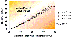
The results from this simple model are shown in Figures 4 and 5. Figure 4 shows the impact of changing the PCM thickness for a 25°C ambient temperature (heat sink). The phase change point of Glauber’s Salt is also indicated on the curve. The curve shows (for an 18 inch vertical height) the maximum heat flux possible from the surface for the given inner wall temperature. The maximum inner wall temperature must be less than the phase change temperature of the PCM. One can look at the heat flux that must be rejected and determine whether the PCM chosen will solidify. Using Glauber’s Salt would only allow 15 to 17 W/m2 to be removed from the system. If this heat removal rate is not adequate, then the designer must perform more involved analyses to enhance system performance.
 |
 |
|
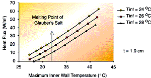
| Figure 4 – The effect of PCM thickness on wall heat flux for steady-state heat rejection as a function of inner wall temperature. The plate height of 18 inches is assumed ñ fins are not considered in this analysis. | Figure 5 – the effect of heat sink temperature on wall heat flux for steady-state heat rejection as a function of inner wall temperature. The plate height of 18 inches is assumed ñ the fins are not considered in this analysis. |
The approach used in generating Figure 4 can also be used to assist in determining which PCM might work for a particular application. Let us say, that for the present application, a steady-state heat rejection rate of 30 W/m2 is required. The inner wall temperature is then approximately 35°C above the phase change point of Glauber’s Salt. The designer can then select another PCM with a higher phase change point, one that changes phase at some point above 35°C. Alternatively, the designer can consider including fins on the outer surface of the heat exchanger, or within the PCM to enhance the heat transfer.
Note that the designer must consider the effects of subcooling on the phase change process. A few degrees of subcooling on a low melting point PCM may make it difficult for a system to solidify in hot climates.
Figure 5 shows the sensitivity of heat flux to changes in the ambient temperature. These changes can indicate that moving an enclosure from one location to another could lead to fatigue failure of the reservoir. Failure of the reservoir will lead to leaks of the PCM and the eventual failure of the electronics.
One last issue of significance is the design of the reservoir to hold the PCM [13]. As the PCMs change from solid to a liquid, there is an increase in the material volume. This volume change induces stress loading in the reservoir. The effect of the thermal cycling can lead to a fatigue failure of the reservoir. Failure of the reservoir ultimately leads to leaks of the PCM and the eventual failure of the electronics.
References
| 1. | McKay, J.R., Coping with Very High Heat Loads in Electronic Telephone Systems of the Future, 10th International Telecommunication Energy Conference (INTELEC), San Diego, CA, USA, Nov. 1988. |
| 2. | Cosley, M.R., Garcia, M.P., L. K. Grzesik, J. Webster, and Marongiu, M.J., Thermal Development of Modular Outdoor Cabinets, presented at 17th International Telecommunication Energy Conference (INTELEC), The Hague, Holland, Oct 29-Nov. 1, 1995. |
| 3. | Marongiu, M.J., Thermal Management of Outdoor Telecommunications Systems, Communications Systems Design Magazine, Oct. 1995, pp. 43-48. |
| 4. | Marongiu, M.J. Closed-Loop Cooling Systems for Telecomm Applications: Their Basics and Implementation, Communications Systems Design Magazine, Jan 97. |
| 5. | Estes, R., Thermal Management of Telecommunications Cabinets, Electronics Cooling Magazine, Vol 3, Nr. 3, September 1997, pp 16-21. |
| 6. | Marongiu, M.J., Kusha, B., and Watwe, A., Computational Studies on Enhanced Thermal Management of Outdoor Enclosures Using Natural Convection in Open Channel on External Walls to be presented at InterPAK 97, Honolulu, HI, June 15017, 1997. |
| 7. | HVAC Systems and Equipment, by The American Society of Heating, Refrigerating and Air Conditioning Engineers (ASHRAE), Atlanta, GA, 1996. |
| 8. | Prudhoe, R. K., And Doukas, L., The Use Of Phase Change Materials (PCMs) and Vacuum Panel Heat Exchangers for Energy Conservation and Thermal Stability of Electronic Equipment Enclosures, 12th International Telecommunication Energy Conference (INTELEC), Florence, Italy, 1990. |
| 9. | Ghiraldi, A., Passive Conditioning Systems For Temperature Control in Telecommunications Equipment Enclosures, 10th International Telecommunication Energy Conference (INTELEC), San Diego, CA, USA, Nov. 1988. |
| 10. | Marongiu, M.J., and Clarksean, R.L., Thermal Management of Electronic Enclosures Under Unsteady Heating/Cooling Conditions using Phase Change Materials (PCM), 1997 National Heat Transfer Conference, Baltimore, Maryland, August 1997. |
| 11. | Stoecker, W.F., Design of Thermal Systems, McGraw-Hill Book Co., 3rd. Ed, New York, NY, 1989. |
| 12. | Incropera, F.P. and Dewitt, D.P., Fundamentals of Heat and Mass Transfer, J. Wiley and Sons Publishing Co., 3rd. Ed., New York, NY, 1991. |
| 13. | Lane, G.A., Solar Heat Storage: Latent Heat Materials Volume II: Technology, CRC Press, Boca Raton, Florida, 1986. |


