Almost everyone working on pressure drop coefficients of perforated plates encounters the work of I.E. Idelchick {1}. A plethora of graphs or equations – some of which are impossible to evaluate quickly – must then be addressed. To simplify this issue for the reader, this month’s Technical Data page has been designed to provide an overview of this information.
When focusing on thin perforated plates with sharp-edged orifices, diagrams 8-1 and 8-5 in [ref. 1] should be consulted. Here a condensed compilation of the pressure drop coefficient (Greek letter ‘zeta’) can be found defined as
=
p / (1/2
u12), with u1 the velocity of air on the upstream face of the plate
and the air density. Various ingredients for the calculation of
(f,Re) as a function of the open area fraction f (0<f<1; f=1 means a fictitious 100% open plate) and the Reynolds number Re=u0 dh /v are provided as an analytical function, in part as graph or table. The Reynolds number must be calculated with the hydraulic diameter dh of an orifice as the length scale and the velocity of air in the hole u0 as the typical velocity. Assuming that the plate contains circular orifices, the geometrical diameter is equal to the hydraulic diameter. The equation of continuity f u0 = u1 can be used to obtain the Reynolds number from the approach velocity u1 as Re= u1 dh /(f v).
Exactly which table or which combination of tables and diagrams is applied depends upon the Re. There are 4 regimes:
| Re>105 |
(1) |
| 30 < Re < 104…105 |
(2) |
| 10 < Re < 25 = |
(3) |
| Re<10 |
(4) |
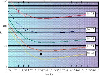
The fully developed turbulent regime is covered by Eq. (1), the laminar one by Eq. (4). Eqs. (2) and (3) are suitable for the transitional regime. For free convective situations Eq. (2) should be used. The original values from [1] were used by the author to elaborate analytical fit functions for all values for f and Re. These functions (f,Re) are plotted in two diagrams: Fig. 1 for 0.1 < f < 0.5 and Fig. 2 for 0.6 < f < 0.95. in a double logarithmic system. We observe that the data does not provide a continuous function
(f=const.,Re) but jumps between the Re-intervals (1) and (4).
Fig. 1. Pressure drop coefficient of perforated plates function of log Re and free area ratio f, for 0.1 < f < 0.5. Note the logarithmic scaling on the vertical axis. The black square denotes the position of the example given in the text.
For example, to calculate (for a plate with holes of diameter d=3 mm, pitch (distance hole center to hole center) s=4 mm and an air velocity of u1 = 0.5 m/s,. f turns out to be f= d2 /(4 s2) = 0.44. Re= u1 d/(f v)
230. Figure 1 can be used to find
4.
Fig.2. Pressure drop coefficient of perforated plates for 0.6 < f < 0.95.
Reference
| 1. | I.E. Idelchik, Flow Resistance, Hemisphere Publishing Corp., New York 1988 |


