Introduction
Recent advances in mobile communications have enabled large scale development of handheld telecommunication products. Such products include cellular phones, pagers, two-way radios, personal digital assistants (PDAs), and other wireless and wireline equipment. The technological enhancements at device, package, and system levels have resulted in increased functionality and decreased form factors of handheld electronic systems. Typically, the handheld products are housed in sealed cases with space being a premium. Air gaps within the enclosure must be kept to a minimum. Much of the heat generated in IC packages is first conducted into printed circuit boards (PCBs), then transported to the housing interior walls by conduction, convection through air and radiative processes, depending on the specifics of the enclosure. The heat must then be conducted through the case walls, and finally removed to the ambient. With the advent of smaller enclosures, higher digital clock speeds, greater numbers of power emitting devices and shorter design cycle times, thermal management becomes critical and must be considered early in the design cycle. Problems of overheating on the ear-piece of cellular phones or on the battery side of portable radios represent just one challenge in the thermal design of the system.
Various handheld products share similar thermal requirements. Most pagers in the consumer market serve as receivers and their active components dissipate low power (a few milliwatts) over a short operational time (several milliseconds). For this kind of a system cooling is not a concern. However, new generations of the pagers have added functionality in the form of voice paging, two-way paging, large display and fax/modem capabilities. These new pagers transmit signals with a power dissipation of approximately 1 watt over an extended period of operation. Cellular phones are becoming an essential part of personal and global wireless communications. With the advent of global satellite communication systems, such as IRIDIUM®, and the advances in consumer electronics, there is an industry trend to add more functionality into the phones, while constantly reducing their size and weight. The highest power dissipating component in the phone is the Power Amplifier (PA). The PA can dissipate power in the range of 1-3 watts. PAs and other ICs are mounted either on a single motherboard or on a motherboard along with a number of daughter boards. Since these electronic packages, particularly the PAs, are assembled in small, confined enclosures, the stand alone thermal performance of the packages does not guarantee similar levels of performance in the phone. A system level solution is required.
The requirements for two-way radios are similar to cellular phones except the enclosure and the gaps between the boards and the case are slightly larger. Air gaps are typically less than 3 mm between PCBs, electronic components, shields, and the external housing. The external housing is normally sealed and does not allow ambient air to freely circulate inside. The power dissipation of the PAs in the radio is comparable to or larger than in the cellular phone.
Due to the commonality of physical structure, design consideration, heat transfer mechanisms, and power consumption, handheld telecommunication product thermal characteristics are similar and can be generalized. Recently, thermal analyses have been performed on cellular phones both numerically and experimentally [References 1, 2]. The following sections review these studies and provide readers with an insight into thermal management technology.
Thermal Management of a Cellular Phone
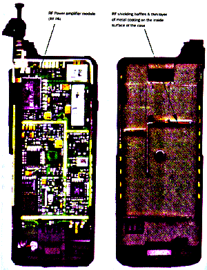
A typical cellular phone is shown in Figure 1. The phone case is a sealed enclosure. The interior consists of a single printed circuit board (motherboard) with surface mount IC packages and other components. Figure 1(a) shows the RF side of the motherboard along with the PA. Figure 1(b) displays the interior view of the rear half of the case with RF shielding baffles and a thin layer of metal coating. These baffles effectively block any air flow between the compartments. The average gap between the components and the case is approximately 1 to 2 mm. The battery is located behind the case in Figure 1(b).
| (a) Interior RF side of the motherboard | (b) Interior or back case |
Figure 1: Inside view of a cellular phone.
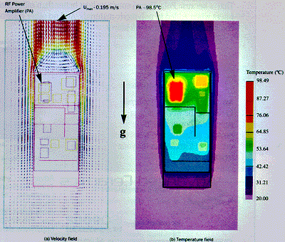
CFD Simulation: In Reference 1, a three-dimensional conjugate heat transfer problem was solved to determine the thermal and flow characteristics in a cellular phone. Methods of computational fluid dynamics were used to solve this problem. A commercial thermal analysis software was used [Reference 3]. In the analysis, the internal radiation was ignored since the interior case walls were plated with a low emissivity material. Typical results are shown in Figure 2. This is based on a power dissipation of 1 watt from the PA, with the remaining components dissipating a total of 1 watt. The simulation predicts the external flow velocities up to ~0.2 m/s, while internal flows are nearly negligible (0.02 m/s maximum velocity), as illustrated in Figure 2(a). The lack of any significant internal fluid motion indicates that the viscous forces are dominating the fluid dynamics due to the small gaps between the circuit board and the case walls. Thus, the predominant mode of heat transfer inside the phone case occurs by conduction. This was verified by calculating the Grashof number based on the gap between the circuit board and the case wall, using the temperature difference between the PA and the case wall. The estimated Grashof number is in the range of 100-300 which implied a conduction regime [Reference 4]. The authors in Reference 1 also simulated a scenario with openings on the top and bottom surfaces of the phone case (the vents occupying ~10% of these case surfaces). It showed no reduction on component temperatures. Figure 2(b) displays the temperature field with the maximum value occurring of 98.5°C in the amplifier module.
Figure 2: simulated results for a free convection cooled cellular phone
The above results suggest that while performing thermal analysis on cellular phones (or on other handheld products with similar physical geometry), the heat transfer process in the internal air gaps can be modeled as gaseous conduction. However, another study [Reference 5] indicated that in some portable radios, radiation from the board to the inner surface of the housing plays an important role in heat transfer.
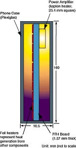
Experimental Evaluation of a Cellular Phone Mock-up: Since previous studies have demonstrated that conduction is the dominant mode of heat transfer in the phone case; thermal management shall therefore focus on reducing conductive thermal resistance. Reference 2 reports an experimental evaluation of the thermal performance of and cooling enhancements to a mock-up cellular phone. Besides the base case (without enhancements), two methods of system-level thermal enhancement have been investigated; the creation of a high conductivity solid conduction path between the PA and the enclosure wall; the addition of a high performance heat spreader to the case wall; and a combination of the two methods. Figure 3 shows the schematic diagram of the mock-up system. The external dimensions of the system housing are 16.0 cm x 7.0 cm x 1.05 cm and the wall thickness is 0.16 cm. The FR4 board without any copper traces and copper planes is located in the middle of the housing with a thickness of 1.57 mm. There is a 3 mm air gap between each side of the board and the phone case. A kapton heater was attached to one side of the board to represent the PA. Ten foil heaters were attached to the back side of the board representing power dissipation from other components (a total power dissipation of 1 watt).
Figure 3: Schematic diagram of the mock-up of a cellular phone
The solid conduction path between the PA and the system housing can be either a metal block, or a thermally conductive pad (epoxy or silicone with a thermal conductivity of ~2 W/mK), a metal spring (~0.8 mm thick), or a thin metal foil (~0.04 mm thick). The material for metal block, spring, or foil could be either copper or aluminum. The metal block, conductive pad, or spring is simply inserted into the gap and the contact is maintained by the press fit. An adhesive tape may be required to attach the foil to the PA and housing. The metal foil can also be used as a heat spreader on the inside surface of the system case. If the power dissipated by the PA can be effectively transferred to the case wall (such as by a solid conduction path), then the heat spreader can quickly distribute the local heat flux over larger area, reducing component temperatures.
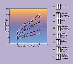
Results of the experiment are summarized in Figure 4. The average experimental uncertainty is ±4%. The least effective enhancement was made by positioning the thermal pad between the board (on the back side of the PA) and the case. With the thermal pad directly contacting the PA, it reduced PA temperature by 34%. The copper spring, due to its higher thermal conductivity and larger heat transfer cross-sectional area provided the best solid conduction path. The copper foil provided an intermediate enhancement. In addition to the solid conduction path, adding the heat spreader to the case further reduced the PA temperature by an average of 26%. A combination of a thin metallic spring and a heat spreader on the enclosure provided the highest enhancement with a 68% reduction in PA temperature.
Figure 4: A comparison of PA temperature for various thermal enhancement techniques
Summary
Handheld telecommunication products have unique thermal characteristics due to their compact structure, high power density, and limited freedom for thermal enhancement. This article chose cellular phones as an example and reviewed some current works on the thermal management technology. CFD modeling indicates air circulation inside the phone can be ignored and the heat transfer inside the housing can be treated as a solid conduction problem. Component temperatures can be reduced significantly by introducing a direct solid conduction path between the component and the internal case and adding a heat spreader to the internal case. However, weight in particular is an issue in such applications. Improvements on material thermal properties and enhancing internal radiative transport also play an important role in thermal management. Finally, recent work done by Georgia Tech. [Reference 6] using synthetic jet technology to promote active cooling in a cellular phone mock-up demonstrates another innovative thermal solution.
Acknowledgments
The authors would like to thank Dr. Jesse Galloway, Dr. Mali Mahalingam, and Mr. Vern Hause of Motorola for their valuable technical input.
References
| 1. | Lee, T. Y., Chambers, B., and Mahalingam, M., “Application of CFD Technology to Electronic Thermal Management” , IEEE Transactions on Components, Packaging, and Manufacturing Technology-Part B, Vol. 18, No. 3, pp. 511-520, August, 1995. |
| 2. | Ramakrishna, K., Lee, T., Hause, J., Chambers, B., and Mahalingam, M., “Experimental Evaluation of Thermal Performance of and Cooling Enhancements to a Hand-held Portable Electronic System”, in Process, Enhanced and Multiphase Heat Transfer: A Festschrift for A. E. Bergles, Proc. of an A. E. Bergles Symposium held at Georgia Institute of Technology, Atlanta, GA (November 16, 1996), pp. 217-226, Begell House, Inc., New York, NY, 1997. |
| 3. | Flotherm, V. 1.4, Flomerics Limited, Surrey, England. |
| 4. | Holman, J. P., Heat Transfer, pp. 255-260, McGraw-Hill, 1976. |
| 5. | Galloway, J. E., “Thermal Analysis Strategy for Portable Electronic Devices”, Motorola Internal Report, 1997. |
| 6. | Minichiello, A. L., Hartley, J. G., Glezer, A., and Black, W. Z, “Thermal Management of Sealed Electronic Enclosures using Synthetic Jet Technology”, Advances in Electronic Packaging 1997, Proceedings of the InterPACK’ 97, EEP-Vol. 19-2, Vol. 2, pp. 1809-1812. |


