Thermal Design is one of the most challenging aspects of computer system design. This is definitely the case when it comes to designing for “fault tolerance” and “high availability” in high-speed multiprocessor-based systems. The inherent challenges associated with fault tolerance not only bring demanding design requirements but headaches as well. The term fault tolerance describes computer systems containing redundant hardware/software features, which enable the system as a whole to tolerate a critical failure while at the same time not affecting the availability of the system to function.
Fault tolerance/high availability is a desirable, and often necessary, feature for certain niche markets/customers within the computer industry. These markets include telecommunications, gaming, airline reservations, enhanced emergency services (911), ATM, banking, and exchange trading. All of these markets share one thing in common: they cannot tolerate down time. These markets are called critical on-line-transaction businesses, since down time directly correlates with severe loss in revenue and/or non-availability of computing resources that can result in dire human consequences.
Fault tolerance, in basic terms, is achieved by building two computers into one. The two are linked by hardware and software cross bridges which permit the two to act as one via parallel partner processing. The same convention holds true for the thermal design engineer who must abide by the same rule as the power, analog, logic, media storage, and software designers. That rule is:
“No single point of failure in any sub-system can result in
the loss of functionality or availability of the system.”
This governing rule of fault tolerance poses a daunting challenge for the thermal designer because it eliminates from the design process various degrees of freedom that are commonly available to thermal engineers designing non-fault tolerant systems. Specifically, the cooling system itself must be fault tolerant. High availability systems are also governed by this rule, although to a somewhat lesser extent.
In general, primary cooling to these types of computer systems is achieved via forced air convection. Liquid cooled systems exist but are limited to specific applications and, therefore, are not the focus of this article. The markets previously identified as being critical on-line-transaction typically demand cooling systems that are of simplified design, customer replaceable/upgradeable, and robust in terms of redundancy. Furthermore, cooling system designs must adapt to various human interactive events, such as hot plug air mover replacement, field upgrade heat sink attachment, etc.
The thermal designer is also challenged by the inherent complications involved with meeting the bus length and timing issues associated with the duplicated and parallel processor/logic/chip sets present throughout the system. With the implementation of higher-powered ASICS and CPU chip/module designs, component placement and attention to air flow delivery are of paramount concern. More specifically, the localized thermal influences of one CPU on another result because redundant pairs must reside in close proximity to each other for timing purposes. These concerns, coupled with manufacturing efforts to make cooling system components turn-key type items, ensure a never-ending obstacle course of challenges through which the thermal designer must navigate.
Design Approach
In a fault tolerant/high availability design, thermal design engineers often make their most critical decisions at the initial stages of product concept design when governing boundary conditions of thermal design are, for the most part, determined. Such boundary conditions include:
- General airflow delivery scheme (vertical, front-back, pressurize/evacuate etc.).
- Placement and location of critical elements and components throughout the system.
- System environment requirements (computer room, open office, central office, etc.).
Choice of system environment is critical because, by default, it sets thermal boundary conditions, such as maximum ambient temperature and audible noise levels. After selection is made, boundary conditions are non-negotiable, because these parameters are governed by external agencies such as OSHA, NEBS, and ISO.
Thermal engineers have the greatest impact on the system architecture at these early stages of product design. Also at this time, negotiation skills and tactics become as meaningful as engineering skills. Thermal engineers must be effective negotiators when it comes to guiding and persuading other engineering entities (power, logic, IO, packaging, manufacturing, etc.) to make decisions and choose designs in harmony “watch dogs” because they must always be aware of the ongoing design choices others make.
Those choices may have a dramatic impact on the viability of the thermal design. An example of such a situation may be as menial as a card guide selection for a PCB. To the packaging engineer this may seem a natural choice, but to the thermal engineer it may pose a disruptive effect to the air flow across the leading edge of that PCB. In fault tolerant designs, the redundancy of hardware throughout the system ensures an uphill battle when it comes to lobbying for proper thermal management design features.
Fault tolerant designs are, by nature, high-density power and packaging designs. A typical fault tolerant design can have up to four times the standard interconnect as a non-fault tolerant design of similar size and volume. Interconnect is a major obstacle to the thermal designer due to the high pin count, signal routing, and cable density required to tie parallel logic processes together. High density interconnects yield solid back planes, bulky connectors and cable counts that can reach into the hundreds per cabinet.
Furthermore, the advent of 3.0 Volt semiconductors demands power distribution strategies that often require high amperage cable capacity, which to the thermal designer translates into even more bulky cables. This in turn results in major obstructions to air flow which make it difficult to provide a sufficient volumetric flow rate of air, not to mention the ability to manage the air distribution profile.
Fault tolerant cooling system designs are unique because they are fault tolerant. At the system level this means that proper thermal management must be maintained, even in the event of air mover failure or removal. This is most commonly addressed by compartmentalizing the air movers into CRUs (Customer Replaceable Units), which are each treated as single points of failure. CRUs often contain multiple air movers.
In Stratus designs (The author was formerly employed by Stratus.–Ed.), each system/CRU in the field is tied to the on-board maintenance system, which is itself tied to field monitoring servers located at Stratus’ home base. These systems have a unique “phone home” capability. If there is any kind of field failure, the maintenance system detects and isolates that failure. The system calls home to Stratus and identifies the failure at the CRU level. A replacement CRU is then shipped overnight to the location in need where the customer carries out the hot plug replacement of the broken CRU.
Cooling CRUs are usually duplicated throughout the system to provide functionality in case any cooling CRU is broken or removed from the system. CRU removal is a most challenging design problem since it usually introduces the thermal effects associated with a major violation of the cooling chimney. Chimney is defined as “the primary cabinet or rack cross section through which air travels.” Chimney violations are further complicated by having to deal with a multitude of other compounding thermal events, which can occur in the field. These include coinciding CRU removals, as well as CRU removals during high ambient temperature duration.
Modeling
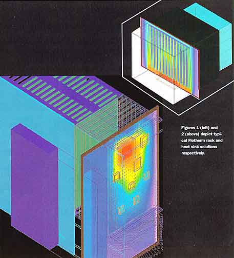
After product concepts are defined and chosen, thermal modeling begins. In the last few years modeling capabilities have improved dramatically. Introduction of new measurement devices for use in air flow measurement, thermal measurement, and associated data acquisition, combined with highly refined software tools such as Flotherm, have greatly enhanced the ability of thermal engineers to produce detailed and accurate models of complex thermal systems. This results in reduced development time and cost. (See Figures 1 and 2.)
 |
Modeling takes place in two forms, physical and CAD. The two types are not mutually exclusive in that they rely heavily on each other for iterative feedback in order to refine their respective solution accuracy within acceptable levels. As mentioned, thermal modeling is an iterative process. Software tools, such as Flotherm, often require critical value inputs, such as loss coefficients and pressure drop estimates, which, for the most part, cannot be calculated or derived from pre-established data. Therefore, the need exists to produce actual physical representations of enclosures, orifices, etc., and to measure experimentally the aforementioned values.
This iterative dependency can be time consuming and often frustrating. Nonetheless, it is inescapable. In the effort to construct a useful and accurate thermal model, the thermal engineer must rely on both forms of modeling to achieve the desired result. It is also worth mentioning that thermal models frequently serve another highly useful purpose. They are often the first and only physical representation of a product in development and are therefore sought by marketing and management to serve as “show and tell” type items. This is extremely important because thermal models can serve as the platforms from which the thermal engineer further negotiates for appropriate thermal design features.
The Challenge of High Powered CPUs
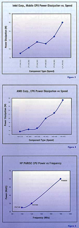
As previously stated, technology trends are driving CPU designs toward higher powered multi-chip module designs. High powered multi-chip modules, such as Intel’s Pentium, Descheuttes, Merced, as well as RISC-based processors from HP, have been and are becoming standard throughout the industry. The quest to thermally manage these types of devices is becoming increasingly more difficult given that demand for increased processor speed continues to grow. The relationship between processor speed and power dissipation ensures ever-increasing power dissipation levels. The result of this speed-power relationship ensures thermal design challenges for years to come. (See Figures 3, 4 and 5.)
 |
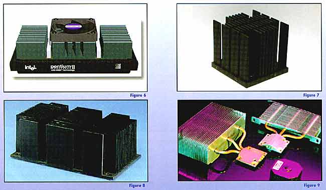
Figures 3, 4 and 5 depict the trend in power dissipation for a variety of processor families (AMD, Intel and HP).Heat sink designs for these types of devices have shifted the paradigm in the thermal solutions marketplace. Conventional thermal technologies can no longer support solutions for high heat flux devices, such as Merced. Merced is expected to dissipate 130 Watts in its first version release (running at 700 MHz). Industry rumors put Merced follow-on “kicker” products at over 1 GHz with power dissipation levels approaching 200 watts. For the most part, thermal design goals for all high powered CPUs will require application-specific and exotic heat sink solutions. Such types include narrow channel, closed loop heat pipe, inverted impingement, and various other forms of dedicated air mover-heat sink integrated solutions. (See Figures 6, 7, 8, and 9.)
 |
Figures 6, 7, 8 and 9 depict examples of dedicated air mover, heat sink and heat pipe designs. The designs shown have effective heatsink-ambient resistance of less than .5oC/Watt.
Noteworthy Technology Improvements
In addition to the aforementioned modeling and software tools, technology improvements in the areas of air movers and thermal interface materials have provided thermal designers with new ammunition to add to their design tool arsenal. Cold flow phase change and other new low impedance thermal interface materials enable thermal designers to depend on low resistance thermal-mechanical joints for heat sink attach. Such innovation at the joint level is welcome since it is an often overlooked yet most critical part of a heat sink design.
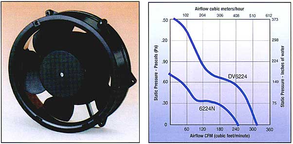
Air mover technology has improved to the point where new air movers are replacing older, more traditional designs. For example, Papst’s new DV series units offer a 2-3 times improvement in terms of volumetric flow rate supplied as well as the ability to overcome impedance. The DV series units are same form factor (size) as the commonplace 6.75″ diameter tube axial fan, which is a workhorse air mover found throughout the telco computer industry. These types of new products in the thermal marketplace will enable thermal designers to further push the envelope of forced convection cooling. (See Figures 10 and 11.)

Looking Ahead
As we prepare to turn the calendar on a new century, the future of thermal design holds great promise; specifically, its role in system level computer design. This is especially the case in the marketplace for fault tolerant and high availability systems. Technology and packaging trends all but guarantee a never-ending set of thermal design challenges, which must be met in order for the high availability marketplace to keep pace with the explosion of new semiconductor development and its associated appetite for power. All of these factors ensure that thermal design will continue to play an ever-growing part in the direction of computer system design and product definition.


