In the last decade, we’ve come a long way in the application of thermal analysis to the design of electronics. And there’s no sign of the pace of innovation changing. Engineers are still being challenged to build faster, smaller and cheaper products in ever-decreasing design times. Fortunately, the engineering software industry has been able to respond by providing tools that help designers both analyze and understand the complex fluid flow and heat transfer mechanisms within their equipment.
In this article, I’ll be giving a personal perspective on the future of thermal analysis. I’ll start by looking at the changes in the underlying technology then chance some predictions on what the next 5 to 10 years will have to offer. In particular, I’ll talk about:
- How advances in hardware and software are affecting thermal analysis tools.
- The realization of the dream of practical component characterization.
- Integration of thermal analysis with EDA and MCAD systems, and other analysis tools.
- The impact of the Internet and the emergence of Web-based applications.
Figure 1. Thermal analysis today from IC package to equipment room … and everything in between.
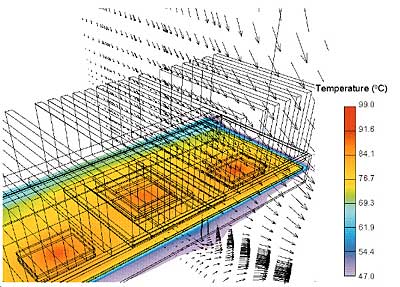 |
a) Package-Level Analysis
Pentium®II Processor & Heatsink.
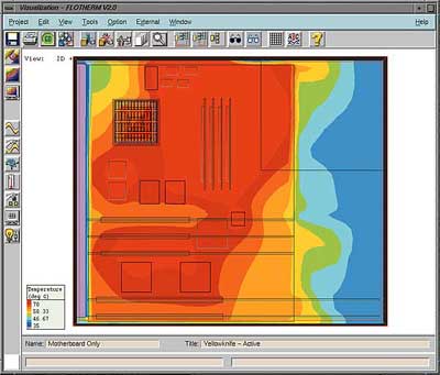 |
b) Board-Level Analysis
Temperatures in the motherboard of the Motorola PowerPC® Reference Platform “Yellowknife”.
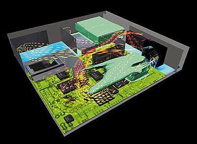 |
c) System-Level Analysis
Airflows through a PC Chassis.
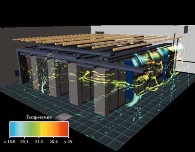 |
d) Room-Level Analysis
A Telecommunications Switching Room.
Advances in Hardware and Software
Perhaps the biggest changes that we are seeing today result from the ready availability of processing power that, 10 years ago, would have been unimaginable. Ironically, the very same Moore’s Law that predicts the growth in processor speed, also predicts the increases in dissipated power, which are heightening the need for thermal modeling!
Today’s computers are orders of magnitude faster than their ancestors a decade ago. The results can be seen everywhere from increasingly sophisticated solvers to the high-end 3D graphics that are now commonplace. However, we have also seen improvements to the software. Tuning of software algorithms have made significant improvements in processing time.
In certain areas, more radical techniques have produced worthwhile improvements. For instance, a Monte Carlo method has recently been employed in one tool to determine radiation exchange factors for the highly cluttered geometries typical of electronics systems with order of magnitude improvements in run-time compared to more conventional analytical techniques optimized for sparsely populated geometries.
Computer operating systems are also evolving and, like it or not, the trend is inexorable: Windows NT has all but won the battle for the engineering desktop. In fact, a recent poll of thermal analysts attending the 1999 FLOTHERM User Conference showed that over 80% of them had access to Windows NT on their desktops, compared with 30% having access to Solaris machines (the next biggest group).
Although there is much talk about the emergence of Linux, it is hard to believe that it will find more than a niche role in engineering companies as a server platform and, in the context of thermal analysis, possibly as a “calculation engine”. It is unlikely to displace Windows NT from the desktop.
The prevalence of Windows NT is also fueling the growth of “Intel-based” hardware, including compatible processors from AMD and Cyrix. Increasingly, we see multi-processor machines becoming standard on engineers’ desktops. To take full advantage of the additional processing power that they offer, software is being rewritten to be multi-threaded and even, whenever possible, fully parallelized (Figure 2-overleaf).
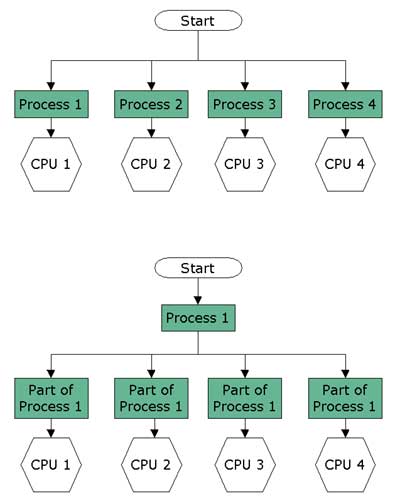 |
Figure 2. Multi-threading (top) and parallelization (bottom).But speed itself isn’t the ultimate goal. It merely allows a designer to explore a wider design-space in order to identify problem areas and to develop an optimum solution. Using thermal modeling techniques to model “what-if” scenarios makes it much easier and faster for engineers to determine the effects of repositioning objects, such as vents, fans and heatsinks, for a given product design before physical prototyping begins.
Unfortunately, the very success of thermal analysis creates another problem, which is the sheer volume of data which can (and will) be produced. The management of this data will become an increasingly taxing problem that will be addressed by a new breed of tools. These tools will allow not only rapid generation of parametric cases, but also facilitate the post-processing and comparison of multiple runs so that the designer can concentrate on the optimization of the product design.
Finally, while optimization techniques have already been applied to problems, such as stress analysis and coupled thermal/stress problems, applications involving fluid motion have proven far more difficult due to the strong non-linear coupling and the large number of calculations involved. The continuing pace of computer hardware development will change this and will make it possible to apply optimization techniques to practical design problems, such as the positioning of fans, design of heatsinks, etc.
My Predictions:
- Increases in processing power will continue to fuel the explosive growth in analysis capabilities. Today’s fastest workstations will be obsolete by the end of 2003, replaced by machines with power we can only dream of today!
- Windows NT (and its descendants) will – despite the emergence of Linux in specialized applications – dominate engineers’ desktops.
- Parallel processing and multi-threading will become commonplace in analysis tools as multi-processor “Wintel” machines become the norm.
- Watch out for a new range of data management tools, which will help users both organize analysis data and post-process parametric runs, allowing them to harness the raw power of the new hardware.
- Later in the next decade, keep an eye out for the first practical examples of automatic optimization involving fluid motion.
Practical Component Characterization
It has been known for a long time that existing ja component characterization techniques are inadequate. The errors are too great and, with the advent of Ball Grid Array (BGA) and Chip Scale Packaging (CSP) technology, the effect of the board cannot be ignored. Systems designers want and need a quick estimating technique.The European DELPHI and SEED projects have mapped out a way forward by identifying both a methodology for determining environmentally independent component thermal characteristics and experimental techniques to validate the models. But it will be some time before the full infrastructure to support these techniques is available, including:
- Analysis tools to determine the models.
- Implementation of the models in system-level design tools.
- Support for the models in component libraries and board layout files.
An intermediate step is likely to precede the adoption of the full DELPHI models. Two-resistor ( jc +
jb) models – although the subject of some controversy – are part-way to full DELPHI models and can be determined either by analysis tools or experimental techniques. Although they are not fully environmentally independent, they are a significant improvement over existing methods (
ja) and can already be utilized in system-level analysis tools and included in board layout files.
My Predictions:
- Environmentally independent component thermal models will become commonplace during the middle years of the next decade.
- In the meantime, 2-resistor models will provide a partial solution to system designer’s needs for a quick estimating technique.
Integration with EDA, MCAD and Other Analysis Tools
The true benefits of vendor-supplied component characteristic data will really only be felt when thermal analysis tools work closely with the Electronic Design Automation (EDA) tools used to develop board layouts. Efforts to integrate these tools in the past have been hindered by the lack of a common standard for data transfer with each EDA vendor using their own proprietary data format. Fortunately, the emergence of IDF in the mid-1990’s means that this is now a far less difficult task. IDF files are not without their problems, including:
- Sparse support for component thermal data (nothing at Level 2 and only 2-resistor models in Level 3).
- Excessive detail requiring intelligent filtering by the system-level analysis tool.
However, IDF Level 2 is supported by all major EDA vendors, and the picture is far brighter than it was two or three years ago.
Finally I should add a concern that has been voiced many times with no satisfactory answer to date – where do we get accurate power figures? If we’re going to spend a great deal of effort characterizing components and building accurate models of the system, we ought to do something more sophisticated than assume the maximum rated power for all components! Thermal analysts must start looking critically at the accuracy of the tools used to provide these figures and develop means to import these values from EDA systems into their simulations.
A similar dilemma is faced in integrating thermal analysis tools with MCAD. MCAD file formats have always been troublesome as anyone who has tried to move data from one system to another will attest. However, the past few years have seen the situation improve with the stabilization of IGES as a global format, and the emergence of alternatives, such as SAT (for ACIS-based tools), STL and even VRML. Somewhat surprisingly, the predicted trend towards STEP (ISO 10303) has not materialized – at least not among design engineers in the electronics industry. I would expect IGES to continue to dominate this area as we move into the next century.
But filtering of excessive detail in the MCAD file (such as radii, fillets, draft angles and small holes) remains the most critical problem. A certain degree of simplification can be achieved in the CAD tool itself. But sometimes the features are so deeply embedded in the solid model that this is difficult to achieve.
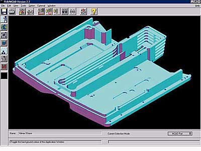
So a new breed of interface tools, based on solid modeling kernels such as ACIS, have been developed to enable the thermal analyst to load, simplify and then enhance the MCAD geometry ready for analysis (Figure 3).
 |
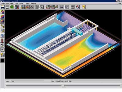 |
Figure 3. Use of an advanced MCAD ionterface to simplify IGES data; (top) before simplification and (bottom) after simplification and thermal analysis.A further improvement is the gradual introduction of “Healing Technology”. This is advanced intelligence built into software that can read poorly composed MCAD files and “mend” surfaces that don’t quite match up. Such tools are absolutely essential if thermal analysis tools are to be closely integrated with MCAD systems.
Thermal analysis doesn’t exist in isolation from other analysis tools. In some areas, the links are strong and have long been acknowledged. For example, in the IC packaging industry, calculation of thermally-induced stresses have always been a critical part of the design process to ensure that the package reliability figures are met. Such coupled analysis using FEA tools is commonplace at package level. Its extension to board level may be a natural consequence of the increasing integration of EDA and thermal analysis tools through the medium of IDF (see above).
Another area where links are strong is EMI/EMC. At the package level, a design that may be excellent for electrical performance may be thermally poor or may be far too expensive to manufacture. Trade-offs are inevitable in this situation and tools are beginning to come to market that allow package designers to use a common data definition to assess the effect of design changes on both thermal and electrical performance.
There are other areas of electronics where thermal and EMI/EMC issues are closely linked. In the telecommunications and networking industries, a cabinet of high speed switching equipment may be installed in close proximity to other equipment and so must be shielded to prevent both emission and reception of electromagnetic radiation. Unfortunately, the act of shielding the shelves has an adverse effect on the natural convection cooling, which is becoming a requirement for designers.
Since there are many similarities in both the physics and the definition of the EMI/EMC problems, I would expect this to be leveraged over the next ten years as combined EMI/EMC and thermal analysis software is produced based on a common data definition.
My Predictions:
- IDF 3 will become commonplace for EDA integration. IDF 4 will remain in the shadow because of its radical differences with IDF 2 and 3.
- IGES remains the primary data file exchange format for MCAD. STEP might emerge in the latter part of the decade.
- MCAD healing and simplification technology will become an intrinsic part of thermal analysis software.
- Stress and thermal analysis will converge in board-level analysis tools as EDA integration increases.
- Look for the extension of thermal analysis to include EMI/EMC – particularly in telecommunications and networking applications – based on a common underlying data model and GUI.
The Impact of the Internet
You can’t pick up a paper today without reading about the impact of Internet on businesses such as banking, share trading, book sellers, etc. And the Internet is beginning to make its mark in the field of thermal modeling. Since its origins in the early 1990’s, the Internet has passed through many stages. Today forward-thinking software companies keep their users fully up-to-date with support information, software patches, bug lists, and modeling advice.
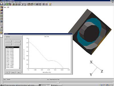
More recently, thermal models of parts such as processors, fans and heatsinks have been posted on Web sites for thermal analysts to download and to use in their models (Figure 4-overleaf). In addition, libraries of commercially sensitive thermal data are available directly from leading manufacturers, such as Intel and Motorola.
 |
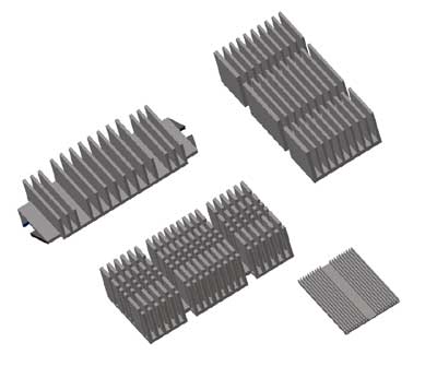 |
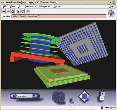
Figure 4 – Examples of library data from the Web: (left) an axial flow fan from PAPST and (right) high performance heatsinks from Johnson Matthey Electronics.But perhaps the most radical changes are only beginning with the development of Web-based applications. These applications, the first of which was seen in late 1998, are accessible to users around the world using a standard Web browser. They can be tailored for specific industry sectors, involve no installation, and present no configuration headaches (Figure 5-overleaf).
 |
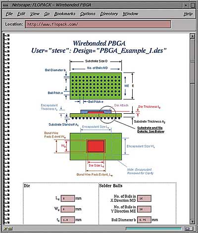 |
Figure 5 – A Web-based application to create and analyze IC package thermal models: (left) VRML visualization of CBGA, PBGA and disk fin heatsink and (right) Web form for creating a CBGA.So what does the Internet hold for the future? Anticipating the evolution of the Internet is even more difficult than predicting changes in thermal management. But here are some trends that I’m seeing today:
- Increasing use of VRML (Virtual Reality Modeling Language) as a method of viewing geometry and (eventually) analysis results.
- The vast potential for XML – “eXtensible Markup Language” (www.xml.org) to integrate thermal analysis tools with new generations of PDM systems based on Internet standards, for example, “WindChill” from PTC (www.ptc.com).
- Web-hosted applications for specific thermal analysis tasks such as heatsink design (e.g., R-Tools from R-Theta [www.r-theta.com]), component thermal analysis (e.g., FLOPACK from Flomerics [www.flopack.com]), or for healing flawed MCAD data files (e.g., 3dmodelserver from Spatial Technology [www.3dmodelserver.com]).
My Predictions:
- More web-based applications will be introduced for parts of the thermal analysis process complementing desktop analysis tools.
- Wide availability of library data will be ensured through vendor and central web sites.
- VRML and XML will become standards for graphics and data exchange respectively.
Conclusions
So what will tomorrow’s thermal analyst be using? Although computing power will yield faster solutions and smoother graphics, I believe that tomorrow’s analysis tools will still be recognizable to today’s engineers. Some of the functionality may migrate to the Web, but this will be transparent to the end-user.
The main difference will be seen in the increasing number of data sources that the analyst will be able to draw on, including importing geometrical and board layout files, Web-based tools for specialized applications and more accurate component thermal models in public and corporate libraries. The end result – models that today take one or two hours to create will take minutes in future.
Some Final Thoughts
If I seem to have been concentrating on areas such as integration with other design and analysis tools, it is because I see these as the areas that will change the most over the next five to ten years. Today’s analysis software tools – whatever their underlying technical basis, gridding system and turbulence model – are all more than capable of calculating flow and temperature fields with a degree of accuracy that is more than acceptable for design purposes. After all, what value is there is a calculation accurate to 0.1°C when the input power levels are 100% out!
The real advances that the next decade will bring are in areas which tangibly and significantly enhance the productivity of thermal designers by making it easier and quicker to assimilate and simplify the varied data sources contributing to the analysis, and to manage and digest the resulting volumes of data.
But if anything is certain about the future, it is that it is unpredictable! And when one tries to look into the future for an industry as dynamic as today’s electronics design industry, one is doomed to almost inevitable failure. If nothing else, I hope that this might spark some thoughts in your own application of thermal analysis to the very real and pressing problems of designing today’s electronic systems. And if you have any predictions of your own, please let me know.


