 |
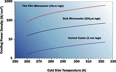
Figure 1. Cooling power density for different T.E. cooler designs
(adaped from Vandersande and Fleurial [6]).
Introduction
Many advances in computer technology have been made possible by increases in the packaging density of electronics. These advances began with the introduction of the transistor in 1947 and continue today with ultra-large scale integration at the chip level coupled with multi-chip modules. The combination of increased power dissipation and increased packaging density led to substantial increases in chip and module heat flux over the past 40 years, particularly in high-end computers. During this time the challenge was to limit chip temperature rise above the ambient coolant temperature to ensure satisfactory circuit operation and reliability.
Throughout this period virtually all commercial computers were designed to operate at temperatures above ambient, generally in the range of 60° to 100°C. However, the potential for low temperature enhancement of CMOS electrical performance has been recognized for some time, going back as far as the late 1960’s. Researchers identified the advantages of operating electronics at low temperatures. These advantages include: faster semiconductor device switching; increased speed due to lower electrical resistance of interconnecting materials; and a reduction in thermally induced failures.
Until recently the only computer to take advantage of the operation of CMOS chips at low temperature was the ETA-10 [1], a large-scale scientific computer. This machine utilized direct immersion cooling of single chip modules immersed in liquid nitrogen. In 1997 IBM announced and shipped the RY5 S/390 mainframe, which uses a conventional refrigeration system to maintain chip temperatures below that of comparable air-cooled systems, but well above cryogenic temperatures. Since then there have been indications that other manufacturers may be developing refrigeration cooled computers.
In addition, the scaling limits of CMOS devices — and how to achieve performance gains as scaling limits are approached — has received increased attention in the semiconductor electronics community. Operation at lower temperature is seen as a means to further extend CMOS performance. These developments not only foreshadow further applications of refrigeration cooling of electronics, but also potential opportunities to apply thermoelectric cooling to computer electronic packages.
Thermoelectric Cooling
Although the principle of thermoelectricity dates back to the discovery of the Peltier effect in 1834 [2], there was little practical application of the phenomenon until the middle 1950s. Prior to then, the poor thermoelectric properties of known materials made them unsuitable for use in a practical refrigerating device. As discussed by Nolas et al. [3], from the mid-1950s to the present the major thermoelectric material design approach was that introduced by A.V. Ioffe, leading to semiconducting compounds such as Bi2Te3, which is currently used in thermoelectric coolers. These materials made possible the development of practical thermoelectric devices for attaining temperatures below ambient without the use of vapor-compression refrigeration.
Thermoelectric coolers offer the potential to enhance the cooling of electronic module packages to reduce chip operating temperatures or to allow higher module powers. Thermoelectric coolers also offer the advantages of being compact, quiet, free of moving parts, and their degree of cooling may be controlled by the current supplied. Unfortunately, compared to vapor-compression refrigeration, they are limited in the heat flux that they can accommodate and exhibit a lower coefficient of performance (COP). These two limitations have generally limited thermoelectrics to niche applications characterized by relatively low heat flux.
In recent years there has been increased interest in the application of thermoelectrics to electronic cooling, accompanied by efforts to improve their performance through the development of new bulk materials and thin film microcoolers. The usefulness of thermoelectric materials for refrigeration is often characterized by the dimensionless product, ZT, of the thermoelectric figure of merit Z and temperature T (in K). The value of the thermoelectric figure of merit is given by
 |
where is the Seebeck coefficient,
is the electrical resistivity, and K is the thermal conductivity.
Fleurial et al. [4] reported that in 1991 JPL started a broad search to identify and develop advanced thermoelectric materials. Among the materials considered, skutterudite and Zn4Sb3-based materials appeared particularly promising and several of these materials are being developed. ZT values equal to or greater than 1 have been obtained for these materials over different ranges of temperature varying from 375° to 975° K. However, to be particularly useful for electronic cooling applications, improvements in ZT are needed over the temperature range of 300° to 325° K or below. Another strategy for enhancing ZT being pursued by researchers at MIT, Harvard, and UCLA focuses on reduced dimensionality as occurs in quantum wells (2D) or quantum wires (1D) [5].
A number of recent papers discussed the potential advantages of thin film thermoelectric coolers. Vandersande and Fleurial [6] proposed to mount high power components on a diamond substrate, which would be the top or cold side substrate of a thin film thermoelectric cooler. They noted that “the main benefit of going to thin film coolers is the dramatic increase in cooling power density since it is inversely proportional to the length of the thermoelectric legs.” As shown in Figure 1, they reported the possibility of achieving cooling power densities above 100 w/cm2. The structure of such a thin film thermoelectric element is shown in Figure 2.
 |
Figure 2. Structure for a thin film thermoelectric device
(adapted from Fleurial and Vandersande [6]).
The heat pumping capacity, Qp, of a thermoelectric cooling module is given by
 |
where N is the number of couples, G is the ratio of cross-sectional area/length of each thermoelectric element, I is the electrical current, and Tc is the cold side temperature in K, and DT is the temperature difference (Th-Tc) between the hot side and cold side of the thermoelectric elements. The heat, Qte, dissipated by a thermoelectric cooling module to perform the electronic pumping action is given by
 |
and the coefficient of performance, COP, is given by
These equations will be used to determine allowable module heat load or chip temperature with thermoelectric enhancement in an example of an MCM cooling application.
MCM Thermoelectric Cooling Application
For the example application, a 126 mm x 126 mm (4.96″ x 4.96″) MCM containing thirty 15 mm x 15 mm (0.59″ x 0.59″) chips was assumed.
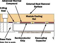 |
Figure 3. Simplified cross-sectional view of a central processor module level package with thermal grease conduciton paths.
A layer of enhanced thermal grease was assumed between the chip and hat as shown in Figure 3. In considering the use of thermoelectric modules to enhance cooling, it is necessary to compare cooling performance with and without thermoelectrics. Figure 4 illustrates the cross-section of a chip site on the MCM with and without a thermoelectric module. Heat flows via a serial path from chip to coolant through the thermal resistances called out in figure 4.
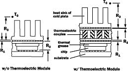 |
Figure 4. Cross-section view of chip site on MCM showing thermal resistances w/ and w/o thermoelectric module augmentation.
The thermoelectric heat pumping equation (2) and heat dissipation equation (3) may be used to determine either allowable module power dissipation, Qm, for a specified chip temperature, Tchip, or chip temperature for a specified module power. Two additional equations relating chip temperature to cold-side temperature (Tc) and hot-side temperature (Thot) to the coolant temperature (To) are required.
The chip temperature is related to the thermoelectric cold-side temperature by
|
where R0 is the sum of thermal resistances across the chip, grease layer, and thickness of the hat, and R1 is the thermal resistance across the interface between the hat and heat sink base or between the hat and the cold-side of the thermoelectric module. The thermoelectric hot-side temperature is related to the coolant temperature, To, by
|
where R2 is the thermal resistance across the interface between the hot-side of the thermoelectric module and the base of the heat sink, and R3 is the thermal resistance from the heat sink base to the cooling fluid.
For steady-state operation, heat pumping capacity, Qp, given in equation (2) will be equal to the module power dissipation term, Qm, in equations (5) and (6). Equations (2), (3), (5), and (6) were combined to obtain equations (7) and (8) shown in Table 1. (see overleaf) Given the material and thermoelectric module parameters, electrical current supplied to the thermoelectric module, and thermal resistances; chip temperature may be determined for a given module power using equation (7). The allowable module power may be determined for a given chip temperature using equation (8). These equations may also be applied to single chip modules by setting module power dissipation equal to chip power dissipation.
For multi-chip modules, application of these equations is restricted to uniform power dissipation on all chips. It should be noted that all of the thermal resistances contained in equations (5), (6), (7), and (8) should be computed on an overall module basis. Accordingly, thermal resistance, R0, should be computed for an individual chip site and then divided by the number of chips on the MCM to convert it to an overall module basis before using it in any of the equations.
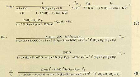 |
Table 1. Chip temperature and allowable power dissipation equations for thermoelectric module augmentation.
A commercially available 62 mm x 62 mm (2.44″ x 2.44″) thermoelectric module was chosen for use in the example presented here. The module chosen was picked because of its size, which would allow four modules to nearly cover the surface of the MCM. The thermoelectric module parameters used in the calculations were:
= 0.0002 volts/K N = 127
= 0.001 ohm-cm G = 0.28 cm.
K = 0.015 watt/cm-K I = 14 amps
Since each thermoelectric module covered one-quarter of the MCM, the thermal resistances and module power were scaled accordingly. The thermal resistance values and coolant reference temperatures used in the calculations were:
R0 = 0.034 K/W
R1 = 0.0054 ”
R2 = 0.0054 ”
R3 = 0.116 ” (air-cooled)
R3 = 0.0168 ” (H2O-cooled)
To = 30 °C ” (air-cooled)
To = 25 °C ” (H2O-cooled)
The values of interface thermal resistances (R1 and R2 ) used were based upon the interface thermal resistance achieved with the IBM ES/9000 TCM cooling technology [7]. Similarly the values used for heat sink (air) and cold plate (H2O-cooled) thermal resistance (R3) were based upon IBM high performance cooling technology scaled for one-quarter of the size of the MCM.
The equations presented in Table 1 were incorporated in a Lotus 1-2-3 spreadsheet and executed with the above values. Comparable equations for the case without thermoelectric augmentation were also included in the spreadsheet. The equation giving chip temperature for a specified module power is
|
and the equation giving allowable module power for a specified chip temperature is
|
An example of the T.E. spreadsheet calculator screen is shown in Figure 5. As noted earlier, thermoelectric cooling modules may be used to reduce chip operating temperatures given a module heat load. The magnitude of temperature reduction for a given design is found by subtracting the results of equation (7) from the results of equation (9). Chip operating temperature reductions, which could be achieved by applying thermoelectric cooling enhancement to the example MCM, are shown in Figure 6.
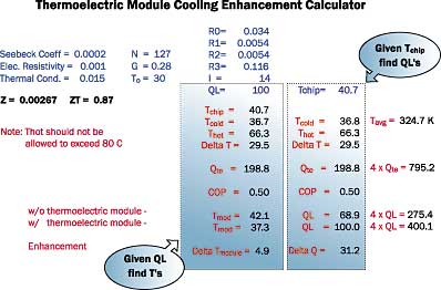 |
Figure 5. Lotus 1-2-3 T.E. spreadsheet calculator screen.
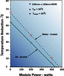 |
Figure 6. Module temperature reduction versus module power for air or water-cooled 126 mm x 126 mm multi-chip modules.
Considering the cost of the thermoelectrics, the added manufacturing process steps, the additional power requirement, and the added reliability risk associated with the thermoelectrics, it is doubtful that they would be considered for anything less than a 20°C reduction. It may be seen that for the example MCM a 20°C temperature reduction would occur at an MCM power of 275 watts for the air-cooled case and at 335 watts for the water-cooled case.
It was also noted earlier that thermoelectric cooling modules may be used to enhance allowable module power dissipation at a given temperature. Comparisons of allowable module power dissipation with and without thermoelectric enhancement are shown in Figure 7 (see overleaf). For the air-cooled case, at a chip temperature of 47°C, the allowable module power dissipation is the same with or without enhancement.
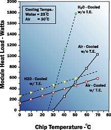 |
Figure 7. comparison of allowable module heat load with and without thermoelectric cooling enhancement.
At higher chip temperatures the allowable module power dissipation is greater without thermoelectric augmentation. A similar situation occurs for the water-cooled case at a chip temperature of 31°C. In both cases the power dissipation at which this occurs at is about 450 to 500 watts. Clearly, the application of thermoelectrics must be carefully assessed to determine if the use of thermoelectrics will be beneficial.
Conclusion
A new dimension has been added to the cooling challenge by the requirement to reduce operating temperatures to achieve enhanced speed. With the continued demand for improved cooling technology to enhance the performance and reliability of CMOS applications, thermoelectric cooling may be considered a potential candidate for cooling enhancement.
The chip temperature (7) and allowable module power (8) equations presented here provide a useful means to perform trade-off analyses to assess whether or not thermoelectric augmentation will be advantageous over conventional cooling techniques. To use these equations, detailed information in terms of the parameters ,
, K, and G pertaining to the thermoelectric module under consideration is required. Unfortunately, today only one thermoelectric vendor provides such information in their data sheets. It is to be hoped that in the future other thermoelectric vendors will also make such information available for users.
As shown in the example, the application of thermoelectric coolers could provide cooling enhancement for a limited range of powers. Unfortunately, in many cases MCM powers may be simply too high for current thermoelectric modules to handle effectively. The current figure of merit, Z, of the available candidate materials, and the coefficient of performance (COP) attainable with existing thermoelectric coolers, need to be increased
Until and unless improvements can be made to enhance heat pumping capability and COP, thermoelectrics will not be a serious candidate for higher power electronic cooling applications. It is hoped that the work being done on development of improved thermoelectric materials and thin film thermoelectrics will eventually alter this situation.
References
1. Krane, R.J., Bar-Cohen, A., Jaeger, R.C., and Gaensslen, F.H., “MOS Electronics and Thermal Control for Cryogenically-Cooled Computer Systems,” in Advances in Thermal Modeling of Electronic Components and Systems, Vol. 2, ASME Press, New York, NY, pp. 185-232, 1990.
2.Godfrey, S., “An Introduction to Thermoelectric Coolers,” Electronics Cooling, Vol. 2, No. 3, pp. 30-33, 1996.
3. Nolas, G.S., Slack, G.A., Cohn, J.L., and Schujman, S.B., “The Next Generation of Thermoelectric Materials,” Proceedings of the 17th International Conference on Thermoelectrics,” pp. 294-297, 1998.
4. Fleurial, J-P., Borshchevsky, A., Caillat, T., and Ewell, R., “New Materials and Devices for Thermoelectric Applications,” IECEC, ACS Paper No. 97419, pp. 1080-1085, 1997.
5. Dresselhaus, M.S., Koga, T., Sun, X., Cronin, S.B., Wang, Cronin, S.B., Wang, K.L., and Chen, G., “Low Dimensional Thermoelectrics,” Proceedings of the 16th International Conference on Thermoelectrics, pp. 12-20, 1997.
6. Vandersande, J.W., and Fleurial, J-P., “Thermal Management of Power Electronics Using Thermoelectric Coolers,” Proceedings of the 15th International Conference on Thermoelectrics, pp. 252-255, 1996.
7. Chu, R.C., and Simons, R.E., “Cooling Technology for High Performance Computers: Design Applications,” in Cooling of Electronic Systems, edited by Kakac, S., Yuncu, H., and Hijikata, K., Kluwer Academic Publishers, Dordrecht, Netherlands, pp. 71-95, 1994.


