The potential for low temperature enhancement of CMOS performance has been recognized for some time, going back as far as the late 1960’s and mid-1970’s. A collection of articles focusing on low temperature electronics is included in the book by Kirschman(1) where a number of researchers [2-6] have identified the advantages of operating electronics at low temperatures. Jaeger (7) also presented advantages of operating CMOS technologies at low temperatures.
Figure 1. Module and chip power trends.
Among the advantages are faster switching times of semiconductor devices, increased circuit speed due to lower electrical resistance of interconnecting materials, and a reduction in thermally induced failures of devices and components. Over the past several years, computer systems have been shipped with refrigeration utilizing the vapor compression cycle to attain low temperatures. Typical evaporator temperatures range from -40�C to 20�C. This paper describes the application of refrigeration to cooling computers and some of the elements related to making the design robust.
Background
The primary desire for driving CMOS chip technologies to lower temperatures is increased performance, either by extracting better performance from existing technologies (thereby avoiding the expense and delay required for advances in design and fabrication, which would be needed to achieve the same performance at room temperature) or by attaining even higher performance with newer technologies. This desire is fueled in the workplace by requirements to do more work in a shorter period of time and by the increasingly competitive nature of the industry to have the highest performing system in the market place.
With the strong move from bipolar to CMOS chip technologies, cooling has now become a strong influence on computer performance. Always cited as the prime electrical property is mobility, which improves at lower temperatures. Transistor switching speed is proportional to the mean carrier velocity in the device and mobility is the ratio of electron or hole velocities to electric field. Mobility increases as temperature decreases due to a reduction of carrier scattering from thermal vibrations of the semiconductor crystal lattice. In addition to mobility the other major benefit in reducing temperature is an exponential reduction in leakage currents.
Achievable performance improvements range from 1 to 3% for every 10�C lower transistor temperature, depending on the doping characteristics of the chip. Raising the junction temperature, on the other hand, enhances bipolar chip performance. Unfortunately the higher temperature is also detrimental to the device reliability. Although the packaging strategy for both CMOS and bipolar technologies involves some form of cooling, only CMOS technology gains in performance as the junction temperature is lowered.
If one uses a vapor compression refrigeration cycle, a 100�C temperature improvement in transistor temperature is not unrealistic, resulting in a 10 to 30% improvement in system performance. This is a mature technology well established in the air conditioning industry. However, the application of this equipment to electronic cooling presents some significant challenges.
Although performance has been the key driver in the use of this technology, the second major reason for designing a system with low temperature cooling is the improvement achieved in reliability to counteract detrimental effects which rise as technology is pushed to the extremes. Many wear out failure mechanisms follow the Arrhenius equation showing that for die temperatures operating in the range of -20�C to 140�C every 10�C decrease in temperature reduces the failure rate by approximately a factor of 2. Therefore a significant improvement should be achieved in chip failure rates with lower temperatures, however this has yet to be substantiated.
The third reason for using low temperature cooling technologies is to maintain temperatures below the functional temperature limit. In many cases, chips are designed to operate at a maximum temperature up to 105�C. If chip powers continue on the path many experts consider beyond the range of air cooling, then low temperature cooling will have to be considered. The trends in heat flux at the module level and the heat dissipated by chips are shown in Figure 1. It is clear from these charts that continued increases in the heat dissipated at the chip and module level will probably continue for at least the next few years.
For these three reasons (increased performance, improved reliability and maintaining chip temperatures below functional limits), major semiconductor and computer companies have shown great interest in low temperature cooling technology during the last couple of years. Some have evolved into major product announcements and eventually shippable products. Intel, Digital Equipment Corporation (now Compaq), AMD, Sun Microsystems, IBM, STS Technologies and Kryotech, Inc have all shown computers at industry shows or shipped products with low temperature cooling that utilizes the vapor compression refrigeration cycle.
In December, 1999, Kryotech teamed with AMD to thermally accelerate the AMD Athlon to 1 GHz with the evaporator cooled to -40�C. This was the first commercially available system to achieve such a performance level, which was achieved by using the performance boost provided by low temperature cooling. Several months earlier, IBM began shipping its third generation refrigerated G6 S/390 large server with even lower temperature processor chips than the prior G4 and G5 systems first shipped in 1997 and 1998, respectively. All three generations (G4, G5 and G6) of IBM’s large servers have processors cooled using vapor compression refrigeration.
All the workstations and servers utilizing low temperature electronic cooling are strong evidence of the race to use this technology for increased system performance, improved reliability and/or maintenance of chip functionality.
Application to High End Servers
In 1993, IBM began transforming its mainframe computer technology from one based on bipolar emitter-coupled logic (ECL) to one based on complementary metal-oxide semiconductor (CMOS) logic. CMOS technology has a tremendous advantage in circuit density. A high-performance central processing unit may be contained on a single CMOS chip, rather than on hundreds of ECL chips. Also, the low switching current of CMOS greatly reduces power consumption, eliminating the need for a complex and expensive water-cooled package.
The IBM S/390 G4 CMOS system, first shipped in 1997, can have 12 processing units, up to two levels of cache and the bus-switching logic packaged in a single multi-chip module (MCM) on one processor board. This delivers performance comparable to that of an IBM 9021-711 bipolar system in which the corresponding logic occupies 56 multi-chip modules on 14 boards. This system was unique in that it was the first such IBM design to employ refrigeration cooling. The decision to employ refrigeration cooling versus other cooling options, such as high flow air cooling or various water cooling schemes, focused on the system performance improvement realized with the refrigeration system.
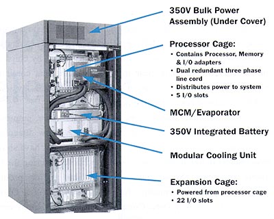
The G4 large server appears in Figure 2. Bulk power for the system, which is shown at the top of the frame, distributes 350 VDC throughout the frame. Below the bulk power is the central electronic complex (CEC) where the MCM, housing 12 processors, is located. Various electronic “book” packages (memory, control modules, DC power supplies, etc.) are mounted on each side of the processor module. Below the CEC are blowers that provide air cooling for all the components in the CEC except the processor module, which is cooled through refrigeration. Below the blowers are two modular refrigeration units (MRUs), which provide cooling via the evaporator mounted on the processor module.
Figure 2. IBM s/390 G4 refrigerated system.
Only one MRU at a time runs during normal operation. Should one MRU fail, it can be replaced via quick connects located at the evaporator. Thus a new MRU can be installed while the system continues to operate. The evaporator mounted on the processor module is redundant in that two independent loops utilizing copper tubes are interleaved through a thick copper plate, each loop attached to separate MRUs. Refrigerant passing through one loop is adequate to cool the MCM (which dissipates a maximum power of 1050 Watts for G4) under all environmental extremes allowed by the system. (The follow-on G5 and G6 systems were packaged in a similar fashion with almost the identical refrigeration system.)
In the bottom of the frame, the I/O electronic books are installed along with the associated blowers to provide the air cooling. Air cooling for the condenser located in the MRUs is provided by air exiting the I/O cage at the bottom of the frame. Air flow through the condenser as well as through the I/O cage is increased for room temperatures above 27�C.
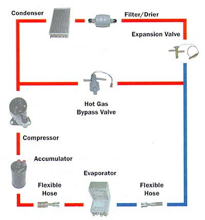
A schematic of the components within the refrigeration system appears in Figure 3. The components of the refrigeration system will now be described.
Figure 3. IBM S/390 G4 refrigeration system components
All components except the evaporator are housed in the MRUs. The components that make up the MRUs were selected to meet heat load requirements of the MCM, environmental conditions of the system, and control aspects required to maintain high system availability. R-134a was selected as the refrigerant because of its environmental compatibility. A rotary compressor with a brushless DC motor provides speed control and, thereby, some temperature control of the refrigeration system.
The high pressure superheated vapor that leaves the compressor passes through a 3-row fin-and-tube condenser where the vapor is reduced to a low temperature subooled liquid. As stated before, the exhaust air from the I/O cage located in the bottom half of the frame provides cooling to the condenser. A filter downstream of the condenser removes any moisture, acids or other contaminants from the refrigerant system.
An externally equalized expansion valve with the bulb mounted on the return line from the evaporator permits the expansion of the liquid to a low temperature, low quality mixture of vapor and liquid entering the evaporator. A microcode-driven control system monitors the evaporator thermistors and pulses the hot gas bypass valve located between the outlet of the compressor and the outlet of the expansion device to maintain the evaporator at nearly a constant temperature.
Normally the compressor operates at 2300 RPM; faster when additional cooling is required. As the refrigerant passes through the evaporator, it begins as a low quality liquid that becomes a slightly superheated vapor at the exit. The amount of superheated vapor exiting the evaporator is controlled by the bulb of the expansion valve attached to the pipe carrying refrigerant away from the evaporator. The bulb is preset to maintain a slight superheat at the evaporator exit. As the temperature at the exit of the evaporator increases, the bulb temperature increases, thereby causing an increase in the refrigerant flow through the expansion valve. To ensure that no liquid returns to the compressor, two accumulators are installed upstream of the compressor.
The evaporator is encased in insulation and sealed with an outer metal cover to prevent moisture infusion and subsequent condensation in the area around the module. In addition, a seal between the evaporator assembly and board inhibits any moisture infusion in the area surrounding the module adjacent to the board.
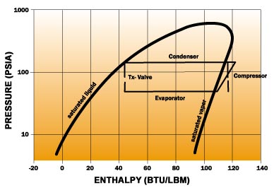
A desiccant installed within the evaporator assembly nearest the board provides further protection. The thermodynamic states for the refrigeration cycle just described appear in Figure 4 for the G4 system.
Figure 4. Thermodynamic cycle for R134a vapor compression cycle used in S/390 G4 server.
In the application of this low temperature technology there are some disadvantages. The three primary ones are cost, power to operate the refrigeration hardware, and packaging space required for the refrigeration components. Each of these must be considered relative to the proposed system design. In many cases, the cost, volume and power required to run the refrigeration system do not justify its implementation. Yet for other systems it may be acceptable.
Depending on the system. the space required for the refrigeration components can vary from 15 to 30% of the system volume. In addition, the percentage of total system cost devoted to cooling hardware can vary with large systems tending to be at the lower end of the spectrum, while workstations are at the upper end. The power required to operate the refrigeration system can be a major consideration.
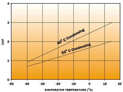
For the refrigeration system employed in S/390 the coefficient of performance (COP) of the vapor compression cycle varies as shown in Figure 5. The 40�C condensing curve refers to the nominal environmental conditions, whereas 55�C condensing temperature refers to the worst case environmental conditions. It is evident that for an operating evaporator temperature of 15�C and nominal room the COP is 3, whereas for a worst case room the COP is approximately 2. (For every 1000 Watts cooled by the refrigeration system, the compressor requires 500 watts input power.)
Figure 5. COP for the S/390 G4 refrigeration cycle (R134a).
Application to Workstations
A number of applications of low temperature cooling with refrigeration have been applied to single processor workstations. In this case, the design is much different than that for the high-end server described above. For workstations, the evaporator temperature is usually much lower to obtain the greatest performance enhancement, typically in the range of -40�C.
The design for the workstation does not include the hot gas bypass valve or accumulators that are shown in Figure 3 for the server. In addition, the low temperature is accomplished with a capillary tube employed in place of the expansion valve in the server application. Even though the cycle is very simple, there are issues similar to that of the server, and these must be carefully addressed; for example, control to accommodate the full range of environmental conditions and, of course, condensation.
The same advantages and disadvantages for applying refrigeration to the server apply to the workstation. Performance, reliability and functionality are all reasons for implementing this technology, while the disadvantages of cost, volume and power apply. In some cases, the sensitivity to these parameters in the workstation is more extreme. However, as evident by the number of systems shipped over the past few years, the advantages can far outweigh the disadvantages.
Other Considerations
Meticulous care must be given to those areas which show temperatures that fall below the dew point. Although the design of the insulation encasing the module, tubes and hoses that experience low temperatures may prevent most of condensation problems, there are invariably some areas that do not permit space for enough insulation. It may therefore be necessary to add heaters in strategic locations to maintain temperatures above the dew point.
Along with maintaining all surfaces above the dew point, it is imperative to exercise the utmost care in sealing the module/evaporator encased with insulation. The seals — to prevent air and moisture from leaking into the low temperature area — must be maintained under temperature cycling conditions and must afford low permeability to moisture passing through the thickness of the seal. Selection of the proper material for adequate sealing and low permeability is important.
The applications described involved an evaporator cooling a single module. In the case of the S/390 module, the cooling was applied to the MCM housing all the processor chips, while the workstation cooled a single chip module. Providing cooling to multiple modules with the refrigeration system requires careful consideration of factors such as serviceability, module power nonuniformities, location of the expansion device, and controlling evaporator temperatures within certain tolerances.
Summary
Cooling designs employing a vapor compression cycle have been successfully employed to provide sub-ambient cooling for high performance CMOS processors in large servers and workstations. The advantages of performance, reliability and maintaining functional temperature limits must be balanced against cost, power and volume required for the refrigeration system.
References
1 Low-Temperature Electronics, 1985, edited by R.K. Kirschman, IEEE Press, New York.
2 Kirschman, R.K., 1985, “Cold Electronics: An Overview,” in Low-Temperature Electronics edited by R.K. Kirschman, IEEE Press, New York, pp. 7-14.
3 Solomon, P. M., “Materials, Devices, and Systems”, in Low-Temperature Electronics edited by R.K. Kirschman, IEEE Press, New York, pp. 16-19.
4 Keyes, R.W., Harris, E.P., and Konnerth, K.L., “The Role of Low Temperature in the Operation of Logic Circuitry”, in Low-Temperature Electronics edited by R.K. Kirschman, IEEE Press, New York, pp. 21-39.
5 Jaeger, R.C. And Gaensslen, F.H., “MOS Devices and Switching Behavior”, in Low-Temperature Electronics edited by R.K. Kirschman, IEEE Press, New York, pp. 90-93.
6 Gaensslen, F.H. And Jaeger, R.C., “Temperature Dependent Threshold Behavior of Depletion Mode Mosfets”, in Low-Temperature Electronics edited by R.K. Kirschman, IEEE Press, New York, pp. 123-130.
7 Jaeger, R.C., 1986, “Development of Low Temperature CMOS for High Performance Computer Systems,” IEEE International Conference on Computer Design: VLSI in Computers, pp. 128-130.


