Over the past decades, the functionality of electronic parts has improved considerably. Increasing power requirements of semiconductor chips make it difficult to keep the temperature below the imposed limits. Thermal management of the chip is one of the main functions of the package. To fully characterize the package thermally, numerical simulations and experimental tests are performed. Numerical models offer advantages because they are cost-effective and can be adjusted quickly. However, it is still necessary to compare the simulation results with experimental data.
Thermal tests can be performed in different test environments. The standardized test environments used at IMEC are the JEDEC box [1], which simulates a still air environment; a cold plate for obtaining higher cooling conditions; and the fluid bath method. Some results for an arbitrary package tested in the three environments, appear in Figure 1.
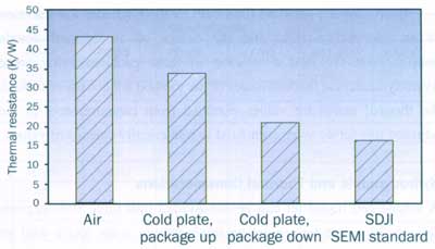 |
Figure 1: An example of thermal resistance values in different test environments.The submerged double jet impingement (SDJI) method has been developed and adjusted by F. Christiaens [2] to perform both steady state and transient measurements. It was inspired by the need for accurate test methods to validate thermal models. Very large heat transfer coefficients are obtained with SDJI, yielding a better accuracy and repeatability of the thermal measurements. The original SDJI configuration was optimized by determining the optimal working fluid and adjusting the geometry of the set-up. The heat transfer coefficient of the new prototype SDJI method has been characterized. The practical implementation and some applications of the method are explained in the article.
Nomenclature
| SDJI: | Submerged Double Jet Impingement |
| CPGA: | Ceramic Pin Grid Array |
| DUT: | Device-Under-Test |
| FOM: | Figure-Of-Merit |
| TSEP: | Temperature Sensitive Electrical Parameter |
| c: | Specific Heat Capacity (J/kgoC) |
| h: | Heat Transfer Coefficient (W/m2K) |
| k: | Thermal Conductivity (W/mK) |
| u: | Dynamic Viscosity (kg/m.sec) |
| p: | Density (kg/m.sec) |
| P: | Steady State Heat Dissipation (W) |
| Rjc: | Junction-to-Case Thermal Resistance (K/W) |
| Rja: | Junction-to-Ambient Thermal Resistance (K/W) |
| Rth: | Thermal Resistance (K/W) |
| Tj: | Junction Temperature (oC) |
| Tref: | Reference Temperature (oC) |
| Zth: | Thermal Impedance (K/W) |
Steady State Thermal Resistance
The thermal performance of packages is traditionally expressed by the thermal resistance value:
 |
where Rth = junction-to-reference thermal resistance (K/W)
Tj = steady state average junction temperature (K)
Tref = reference temperature (K)
P = steady state heat dissipation (W)
Often an indirect measurement technique is needed to determine Tj, as the active chip surface is not accessible for direct temperature sensing. In this case, a temperature sensing electrical parameter (e.g., the forward voltage of a diode) reacts to the applied power step and gives a direct correlation to the junction temperature. Either a local or an average temperature can be measured with indirect techniques. The measurements are nondestructive, very accurate and fast. Therefore, they can serve for both steady state and transient measurements.
The reference temperature is often a case or ambient temperature, denoted by Rjc and Rja respectively, and depends of the environment in which the measurements are performed. The
The SDJI Concept
It is difficult to measure the junction-to-case thermal resistance (Rjc) accurately with the fluid bath method standardized by SEMI [3]. Rjc depends on the flow field around the package, the position of the test board in the thermostatic bath and whether or not the fluid is stirred with an internal or external circulator. The junction-to-ambient thermal resistance (Rja) is less sensitive to the flow field, but more sensitive to the equipment set-up and test board mounting position.
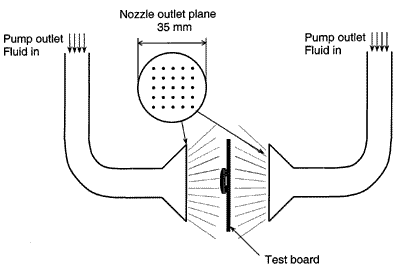
The existing standard method can be improved by increasing the heat transfer coefficient and defining, around the package, a flow field that can easily be created and reproduced. The cooling performance of the bath has been improved by directing a number of parallel impingement jets on the main surfaces of the device and increasing the jet velocity. This leads to a reduction of the Rja values. The external temperature difference between case and fluid is of the same order of magnitude as the temperature error introduced by the thermocouple. Therefore, it is more accurate to measure the fluid temperature close to the device under test (DUT).
 |
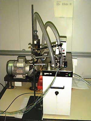 |
Figure 2: Submerged double jet impingement configuration (a) and picture of the fluid bath with dielectric oil (b).In practice, the component is submerged in a fluid bath with dielectric oil. The fluid in the bath is continuously stirred with an internal circulation pump. Two dielectric liquid jets are directed on the main surfaces of the component (Figure 2). An external pump steers the liquid jets through the nozzle outlets and significantly increases the heat flow rate. A thermocouple is placed in the bath very close to the component surface.
Improving the standard fluid bath method includes the selection of an appropriate fluid and the design of an optimal nozzle configuration. To find a solution to these problems, first some hydrodynamic and thermal issues of the method are considered. Next, the thermal resistance values obtained from measurements in the adjusted test set-up were compared to numerically calculated values.
Hydrodynamic and Thermal Considerations
A submerged liquid jet can be subdivided into three flow regions (Figure 3): a free jet region, an impingement zone, and a wall jet region. The orifice diameter, heat source length and nozzle-to-surface separation distance are denoted by d, L and S respectively. The most relevant fundamental experiments with respect to the SDJI configuration have been performed by Womac et al. [4]. They tried to correlate their experimental data in water and FC-77 by considering the heat transfer in the impingement and wall region separately. The following formula (the ‘Womac correlation’) yields the best fit for the two surface regions:
 |
 |
and L* denotes the average length of the wall jet region:
 |
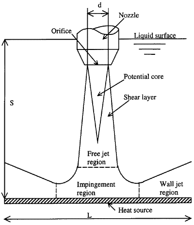 |
Figure 3: Submerged liquid jet.
Improvements of the Test Set-up
The cooling performance of the liquid jets is very sensitive to the nozzle geometry, the liquid velocity and the type of fluid. Keeping the above-mentioned thermal and hydrodynamic considerations in mind, the existing test set-up has been improved.
Selecting an appropriate dielectric liquid for thermal resistance measurements
Next to good thermal properties, the working fluid should possess the following properties:
- Chemically stable and inert
- Non-toxic
- Non-flammable
- Low dielectric constant
- High dielectric strength
- High volume resistivity
The use of water is precluded because of its chemical characteristics. De-ionized water rapidly looses its dielectric strength due to contamination with ions from the environment.
Perfluorinated inert liquids, such as the Fluorinert liquids, made by the 3M Company, are suited for direct liquid cooling because they fulfil the conditions mentioned above. However, some of their thermal properties (e.g., viscosity) are highly dependent on temperature.
Other working liquids that can be considered for thermal measurements with the SDJI method are Baysilone silicon oils manufactured by BAYER. They are clear, non-toxic and cheaper than the Fluorinert liquids. The dielectric strength of the Baysilone and of Fluorinert liquids is comparable. Baysilone oils have a relatively low density, and the thermal conductivity and specific heat are higher than for the Fluorinert liquids. They are chemically compatible with most metals and plastics.
The primary requirement of chemical and electrical compatibility has narrowed the choice to working with fluids with relatively inferior thermal transport properties. A careful fluid selection is of great importance in order to minimize the external case-to-fluid thermal resistance. Therefore, an appropriate fluid thermal figure-of-merit (FOM) is introduced, based on the above-mentioned empirical correlation for submerged liquid jet impingement. A higher value of FOM means better cooling characteristics and, thus, lower external thermal resistance for the
For small L/d, heat transfer predominantly occurs in the impingement region, represented by the following figure-of-merit:
 |
For large L/d, the wall jet region dominates the heat transfer:
 |
with p = density (kg/m3)
k = thermal conductivity (W/mK)
c = specific heat capacity (J/kgoC)
u = dynamic viscosity (kg/m�s)
From Table 1, it can be concluded that the heat transfer in the impingement region (denoted by FOMi) is not very sensitive to the liquid type. However, when the wall jet region dominates heat transfer (FOMwj), a significant difference is observed with the candidate liquids. In the actual SDJI cooling application, the impingement and the wall jet region both dominate the heat transfer. Therefore the geometry of the nozzles has to be taken into account to select the optimal cooling fluid.
| Property (@ 25 °C) | DI- water |
Fluorinert oils | Baysilone oils | |||||||
| FC-72 | FC-84 | FC-77 | FC-40 | FC-43 | FC-70 | HY-M3 | H5S-M5 | H-M50 | ||
| Boiling point (°C) | 100 | 56 | 80 | 97 | 155 | 174 | 215 | 65 | 120 | 250 |
| Pour point (°C) | 0 | -90 | -95 | -95 | -57 | -50 | -25 | -60 | -40 | 20 |
| Density (kg/m3) | 998 | 1680 | 1730 | 1780 | 1870 | 1880 | 1940 | 900 | 920 | 960 |
| Thermal conductivity (W/m°C) | 0.598 | 0.057 | 0.060 | 0.063 | 0.066 | 0.066 | 0.070 | 0.105 | 0.116 | 0.150 |
| Specific heat capacity (J/kg°C) | 4180 | 1046 | 1046 | 1046 | 1046 | 1046 | 1046 | 1510 | 1510 | 1510 |
| Dynamic viscosity (kg/m�s) | 10×10-4 | 6.7×10⁻⁴ | 9.5×10⁻⁴ | 14×10-4 | 41×10-4 | 53×10-4 | 272×10-4 | 27.6×10⁻⁴ | 46×10-4 | 480×10- 4 |
| Dielectric constant @ 1 kHz | 78 | 1.76 | 1.81 | 1.86 | 1.89 | 1.90 | 1.98 | 2.5 | 2.5 | 2.8 |
| Volumetric resistivity (ohm/cm) | 18×106 | 1×10¹⁵ | 1×10¹⁵ | 1.9×10¹⁵ | 4×10¹⁵ | 3.4×10¹⁵ | 2.3×10¹⁵ | 1×10¹⁴ | 1×10¹⁴ | 1×10¹⁵ |
| FOMi | 1300 | 246 | 249 | 250 | 237 | 231 | 207 | 261 | 267 | 251 |
| FOMwj | 82000 | 20472 | 18795 | 16955 | 11800 | 10694 | 5906 | 11785 | 10380 | 4904 |
Table 1: Physical Properties of Fluorinert Liquids (3M) and Baysilone Oils (BAYER).
Designing an Optimal Nozzle Configuration
The hydrodynamic and thermal consideration discussed above only concern single liquid jets. To enhance cooling and reach a higher degree of temperature uniformity, multiple jets can be used. The geometry of the jets is optimized by considering the following parameters:
Experiments in different cooling liquids were performed (water, FC-72 and HY-M3; Figure 4). DI-water has better thermal properties than any other dielectric liquid. The higher liquid density of FC-72 causes an increase in minimal orifice area and thus a decrease in the maximum orifice velocity obtainable at the maximum pressure drop of the pump.
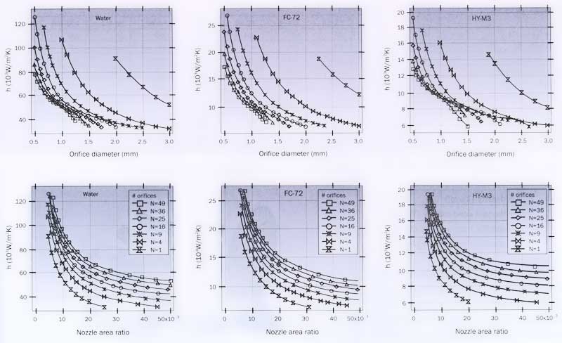
In spite of the lower velocities, the thermal performance of FC-72 is still better than that of HY-M3. Three nozzle geometries have been manufactured (Figure 5) for different package sizes.
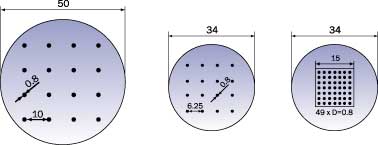 |
Figure 5: Nozzle geometry for different package sizes (dimensions in mm): two 4×4 orifice grids for 25×25 mm2 (a) and 15×15 mm2 (b) packages, and one 7×7 orifice grid for 15×15 mm2 packages (c).In order to characterize the convective heat transfer coefficient of the improved test set-up, thermal experiments have been performed on dummy test structures. This is explained in the following section.
Experimental Evaluation of the Heat Transfer Coefficient
With the three nozzle geometries mentioned above, the heat transfer coefficients have been measured. The surface temperature of some dummy heater components has been measured at different places and averaged to find a uniform value of the heat transfer coefficient. The average convective heat transfer coefficient is defined as follows:
 |
where P = power dissipated in the heater (W)
Tsurface = average surface temperature (oC)
Tfluid = fluid temperature at the nozzle exit (oC)
&


