The three-dimensional shape and irregular nature of electronic component topologies on air-cooled Printed Circuit Boards (PCBs) give rise to complex air flow patterns that have been well documented [1]. Even laminar flows over relatively simple shapes, such as cubical metal blocks simulating electronic components, often exhibit multi-dimensional flow phenomena that include pulsating and vortical structures [2, 3]. To understand the convective heat transfer process in electronic systems, it is vital that the dependence of heat dissipation on such phenomena be examined.
Fluid flow complexity often remains resistive to numerical modeling, leading in some instances to significant prediction errors in component junction temperature [4, 20]. Flow visualization has the potential to yield more insight into a fluid flow or convection problem than any other single method. Many misconceptions can usually be cleared up by flow visualization. It would thus be logical to use it as the first approach to studying a new flow situation. It is important, however, to use the technique most suited to a given problem. Laminar, transitional, and turbulent flows each need a different approach for visualization; similarly, air and liquid flows need to be differentiated, as do boundary layer and core flows, and steady and unsteady flows.
The flow of a fluid may be characterized by one of four terms, which must be carefully defined:
- A streamline is a curve everywhere tangent to the instantaneous velocity vectors, that is, everywhere parallel to the instantaneous flow direction.
- A streakline is the locus of all fluid particles that have passed through a prescribed fixed point during a specific interval of time. An example of a streakline is a line traced by the continuous injection at a certain point of dye, smoke, or bubbles.
- A pathline is the curve traversed by a particular fluid particle during a specified time interval, such as that produced by time-exposure photography of a tracer particle moving in a flow. In steady (time-independent) flow, the streamline, streakline, and pathline that pass through a point are identical. When the flow is unsteady, however, these three lines are generally different.
- A timeline is defined as a set of fluid particles that form a line at a given instant, such as would be obtained in a short-time exposure photograph of a line of hydrogen bubbles released from a wire to trace the velocity profile in a fluid.
While a streamline is mathematically the most tractable, the other three are easier to generate experimentally. Also, a streamline and a timeline are instantaneous entities, while a streakline and a pathline are generated over a period of time.
The literature abounds in flow visualization methods and their application to a very large range of situations. Flow visualization methods can be grouped into two categories; those suited to investigate the complexity of the streamlines just above a surface, or those suited to characterise the surface heat transfer properties. These analyses combined can provide a detailed description of the flow phenomena and their effects on the heat transfer processes. Due to the space constraints in this article, discussion is confined to methods the authors consider most applicable for visualizing air flows in electronic systems. These techniques appear in Table 1 and are discussed in greater detail by Garimella [5].The principle for each technique is described in addition to general implementation details, with examples of visualizations also given.
|
Table 1: Flow Visualization Techniques for Electronic Systems [5]
Air Flow Visualization Methods
Air flows can be qualitatively visualized using smoke entrainment techniques or quantitatively measured using optical methods.
Smoke entrainment is the most common visualization technique for laminar air flows, but has somewhat limited use in turbulent flows due to its rapid diffusion by turbulent mixing. Smoke can be produced from many sources essentially by one of two methods: the smoke-tube and the smoke-wire.
In the smoke-tube method, vaporized oil is used to form a visible whitish cloud of small particles as the hot oil vapor condenses. Consideration must be given to the vortices shed by the smoke probe itself since the most visible small-scale features often arise from the probe’s own wake. This effect is important for probe diameter-based Reynolds numbers exceeding about 15. Since it is not practical to reduce the probe diameter beyond a point and still get a reasonable amount of smoke flow, the smoke can be injected upstream of a convergence section to eliminate wake effects. An alternative method is to inject the smoke through holes in the walls.A key disadvantage to the smoke-tube method is that the smoke is produced hot and rises due to its own buoyancy, thus not following the local flow faithfully. The smoke could be cooled in a long length of tubing from the point of generation before its introduction into the flow to reduce buoyancy effects.
In the smoke-wire method, smoke is generated as a sheet by coating with oil on a thin wire stretched across the flow and heating it with a pulse of current. Almost any wire and power supply may be used in this technique. The oil, however, should be chosen carefully to have a broad boiling plateau, rather than a single temperature, in order to generate good smoke. Model train oil, for example, is suitable.
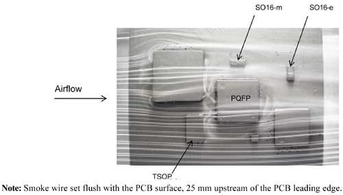
Wire diameters of about 0.1 mm work well; a readily available source for the wire is stripped chromel or alumel thermocouple wire. Once the wire is coated and allowed to sit, the oil draws up into regularly spaced droplets on the wire in less than a minute. Upon being pulsed with current, the droplets produced discrete parallel streaks of white smoke. Type-1964 Fog juice, with a boiling temperature of 276�C, has also been recommended in the literature for producing dense smoke that is non-toxic and non-corrosive. An example of flow visualization obtained over a multi-component PCB using the smoke-wire method is shown in Figure 1.
 |
Figure 1. Experimentally visualized flow fields on a multi-component PCB in a 2m/s air flow, using a smoke-wire method [4,17].Where the smoke-tube method makes use of large quantities of smoke and is used to produce a limited number of streaks that are rather thick (10 mm or more in diameter), the smoke-wire method can be used to produce very thin smoke steaks (about 1 mm).
Optical flow visualization methods have the advantage of being truly non-intrusive. They also do not suffer from any inertia, so that very rapid transients can be studied. Three of the most commonly used techniques include the shadowgraph, Schlieren and interferometry. These index of refraction methods typically rely on the fact that a ray of light is deflected as it passes through density gradients in the flow, with the amount of deflection depending on the path length of the ray through the fluid, the index of refraction of the fluid, and the density gradient. A detailed discussion of these optical methods is available in Goldstein [6].
The shadowgraph and schlieren techniques are generally not readily applicable to the air flows encountered in electronic systems, which are often incompressible due to the relatively small temperature differences and density gradients associated. Interferometry, however, is well suited to quantitatively study such flows, including low speed, free convection boundary layers. A modified version of this technique, called holographic interferometry (HI), has become more popular because it is easier to use and less expensive than classical systems, such as the Mach-Zehnder interferometer.
Particle Image Velocimetry (PIV) has recently become commercially available as an off-the-shelf item and can be used to obtain quantitative flow maps. The technique provides velocity information over a pre-selected plane in a gas or liquid flow field. Unlike the Laser Doppler Velocimetry (LDV) technique, which provides point measurements of velocity and turbulence parameters, PIV provides information at multiple points simultaneously; this enables the calculation of such flow parameters as vorticity and strain rates. The technique is described in detail by Adrian [7].
Liquid Flow Visualization
Flow visualization is usually easier to perform in water than air, and yields results of better quality. As with smoke visualization, dye entrainment is successful mostly in laminar flow. The enhanced mixing in turbulent flow causes the dye streaks to diffuse too rapidly to be of value as tracers. Compared to smoke visualization in air, dye entrainment in liquids is helped by the fact that the mixing between most dyes and water is less intense than between smoke and air [8]. As a result, water-flow tunnels are frequently used to study air flows by testing scaled models at lower velocity, which often permits a better description of the flow to be obtained.
The model is scaled with a different working fluid than air using dimensional analysis. For a treatment of the principals of dimensional analysis and similitude that should be used in applying flow visualization in model experiments, reference can be made to any standard textbook on fluid mechanics, for example, White [9]. The role of similitude in electronics cooling is discussed in detail by Boyle [10].For the flow conditions around a model to be completely similar to those of the prototype, all relevant dimensionless parameters must have the same corresponding values: the model and prototype are then said to possess geometric, kinematic, dynamic and thermal similarity.
However, it is rarely possible in practical experimentation to achieve complete similarity. Instead, an attempt is made to make the model flow as similar to the prototype as feasible with at least the governing non-dimensional parameters maintained identical. Discrepancies in similarity must be taken into account with careful engineering judgment when interpreting the results, which should also be validated by alternative means. Despite these drawbacks, experimentation with scaled models can yield valuable insights into flow behavior.
Water-soluble dyes such as food coloring, potassium permanganate, methylene blue, ink, and fluorescein may be injected with hypodermic needles, or entrained from holes or slots in the walls of a test section to visualize the flow. It is important that the velocity and density of the injected dye be equal to that of the surrounding fluid in order to maintain a stable dye filament and to reduce disturbance to the surrounding flow.
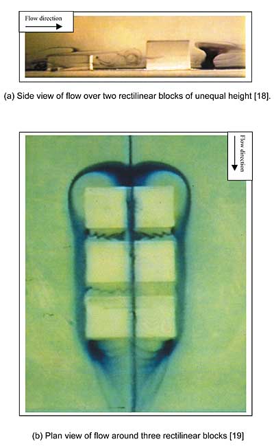
The use of ink streaks in water as a visualization vehicle is illustrated in Figure 2 where this technique was applied to obtain a better resolution of the flow phenomena generated by board mounted modules that simulated air cooled electronic components. By preserving the same Reynolds number of 2300, based on the working section hydraulic diameter, the water free stream velocity was set at 0.05 m/s, versus 0.82 m/s for the same experiments performed in air.This lower velocity permitted easier capture of the main flow features that are typically generated by electronic components. Whereas geometric and kinematic similarities are preserved between these experiments, thermal similarity cannot be achieved as water has a Prandtl number approximately ten times higher than air.
 |
Figure 2. Visualization of the flow phenomena generated by board mounted modules simulating air cooled electronic components using ink streaks in water as a visualization vehicle.
Surface Flow Visualization
For low speed forced convection boundary layers, the momentum, energy and mass conservation steady-state equations are related through the Reynolds analogy [11]. On this basis, surface flow visualization techniques have the potential to offer an understanding of the relationship between flow phenomena and the distribution of the convective heat transfer on a surface, as opposed to smoke flow, which provides an image of the flow above the surface.
Therefore, by visualizing the shear stress or mass transfer patterns on a surface, qualitative information can be gained on the surface heat transfer properties. It should be noted that the Reynolds analogy does not apply at stagnation points, where high heat/mass transfer rates exist, yet shear stress is zero [1,12]. This anomaly should therefore be taken into careful consideration when analyzing surface flow patterns on populated PCBs where multiple stagnation points exist.
Shear stress on a surface exposed to a forced air flow can be qualitatively visualized using paint film techniques, such as the powder based or ink dot methods.
In the powder based method, the characteristic skin friction patterns are created when powder particles suspended in a thin film of oil are aligned to form streaks that develop everywhere tangential to the skin friction vector. Like streamlines in the body of the fluid, skin friction lines cannot cross each other, except at stagnation points where the length of the skin friction vector is zero. Regions on the surface where all the paint is removed represent locations of high shear stress and consequently areas of high convective heat transfer. Conversely, where powder deposits develop, these represent regions of low shear stress and therefore low convective heat transfer.
The ink dot technique consists of drawing ink dots on the matte side of a sheet of frosted Mylar and allowing the ink to dry for a few days. The Mylar sheet is then attached with rubber cement to the surface of interest and sprayed with a thin film of oil of wintergreen. When an air flow is induced over the surface, the ink dissolves in the oil and is carried along with it. The oil evaporates as the air blows past the surface, leaving a permanent ink-streak record behind. Fisher [13] provides practical information on the implementation of this technique.
Mass transfer from a surface can be visualized using either sublimation or evaporation based techniques.
The principle of sublimation methods is based on the fact that a coating of a suitable material on the surface of a body exposed to a forced air flow is sublimed more strongly in a turbulent regime than in a laminar regime. The method works well when the body is a different color than the coating. For instance, if the surface is painted black and naphthalene is used as the subliming substance, it is relatively easy to establish the transition boundary between parts of the surface where the material has completely sublimed and others where material remains.
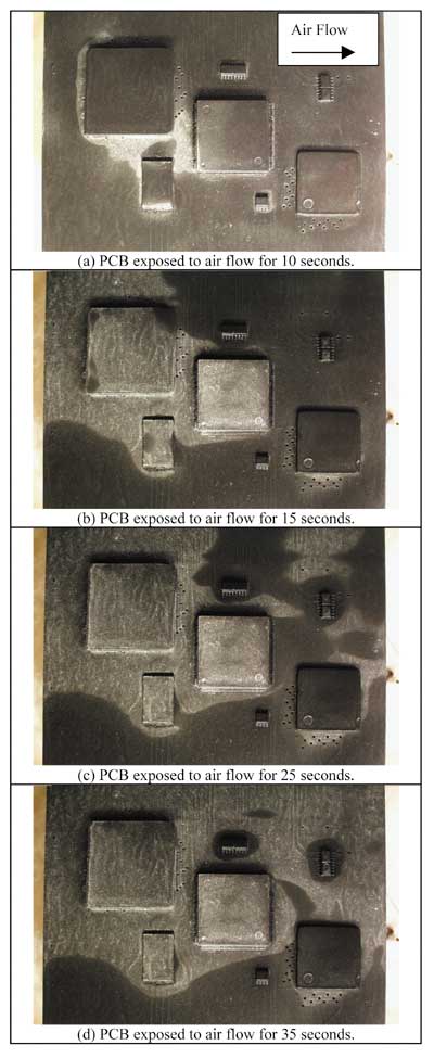
Evaporative coatings of liquids can also be used in a similar way as described in Reznicek [14]. A paint film evaporation sequence is shown in Figure 3, which characterizes the heat transfer properties of the flow fields visualized in Figure 1.
 |
Figure 3. Surface paint flow visualization time sequence on a multi-component PCB in a 2 m/s air flow [4,20]. Brighter regions indicate high heat transfer.To visualize the direction of the flow near a wall, a tuft probe technique can be easily applied. A light and flexible tuft of knitting yarn is attached to the wall using a torque-free hinge. Moffat [15] suggested a pair of interlocking loops of delicate fly-fishing leader material for the hinge. The wall-flow direction may be interpreted from the tuft behavior, since the tuft responds to the flow within a layer approximately the same thickness as the yarn. In a region of separation, the tufts would oscillate or flap.
Streamwise rotation or vorticity would be indicated by the tufts spinning about the hinge forming a narrow cone nearly parallel with the wall. Air speeds should not be less than 1 to 2 m/s for using wall tuft probes, since otherwise the stiffness of the tuft and gravitational effects could affect the observed results [8].There also exists an upper limit of air speed for the use of tuft probes, but this would rarely be of concern in electronics cooling applications. The tuft probe described above may also be used for probing core flows, that is, away from the channel walls in the interior of a flow.
In addition to the visualization method employed, knowledge of elements of photography, choice of recording medium (color or black and white prints or slides, video), lighting methods, and choice of tracer are all integral to the success of the experiment. A variety of photography and illumination techniques are discussed in Mueller [16] for visualization in air and water.
Summary
Flow visualization is a powerful tool that can significantly enhance the understanding of an electronic system thermofluids. A review of flow visualization techniques applicable to air flows in electronic systems has been presented. A wide range of methods are suited to different applications, whether the flow just above a surface needs to be visualized or the surface heat transfer properties characterized.
Acknowledgements
Portions of the material presented in this article were quoted directly from Garimella [5].
References
1. Meinders, E.R., 1998, “Experimental Study of Heat Transfer in Turbulent Flows over Wall-Mounted Cubes, ” Ph.D. Thesis, Faculty of Applied Physics, Delft University of Technology, The Netherlands, pp. 19-36.
2. Boyle, M. T., and Asante, K. A., 1990, “Detailed Film Coefficient Measurement of a Simple Large-Scale Semiconductor Package Geometry,” Proceedings of the Sixth IEEE Semiconductor Thermal and Temperature Measurement Symposium (SEMI-THERM VI), pp. 89-94.
3. Schofield, W. H., and Logan, E., 1990, “Turbulent Shear Flow over Surface Mounted Obstacles,” ASME Journal of Fluids Engineering, Vol. 112, pp. 376-385.
4. Rodgers, P., 2000, “An Experimental Assessment of Numerical Predictive Accuracy For Electronic Component Heat Transfer,” Ph.D. Thesis, University of Limerick, Limerick, Ireland.
5. Garimella, S. V., 1997, “Flow Visualization Methods and their Application in Electronic Systems,” in Thermal Measurement in Electronic Cooling, Azar, K., Ed., CRC Press LLC, New York, pp. 349-385.
6. Goldstein, R. J., 1983, “Optical Systems for Flow Measurement: Shadowgraph, Schlieren, and Interferometric Techniques,” in Fluid Mechanics Measurements, Goldstein, R. J., Ed., Hemisphere, Washington, D. C. pp. 377-422.
7. Adrian, R. J., 1986, “Multi-point Optical Measurements of Simultaneous Vectors in Unsteady Flow – A Review,” International Journal of Heat and Fluid Flow, Vol. 7, No. 2.
8. Merzkirch, W., Ed., 1987, “Flow Visualization,” 2nd ed., Academic Press, New York.
9. White, F. M., 1994, “Fluid Mechanics,” 3rd ed., McGraw Hill, New York.
10. Boyle, M., 1997, “Similitude in Electronics Cooling,” in Thermal Measurement in Electronic Cooling, Azar, K., Ed., CRC Press LLC, New York, pp. 349-385.
11. Incropera, F. P., and De Witt, D. P.,1990, “Fundamentals of Heat and Mass Transfer,” 3rd ed., Wiley, New York, pp. 311-384.
12. Hunt, J. C. R., Abell, C. J., Peterka, J. A., and Woo, H., 1978, “Kinematical Studies of the Flows Around Free or Surface-Mount Obstacles; Applying Topology to Flow Visualization,” Journal of Fluid Mechanics, Vol. 86, Part I, pp. 179-200.
13. Fisher, E. M., 1987, “The Influence of a Horseshoe Vortex on Local Convective Heat Transfer Rates,” M.S. Thesis, Department of Mechanical Engineering, University of California at Berkeley, CA.
14. Reznicek, R., 1989, “Surface Tracing Methods,” in Handbook of Flow Visualization, Yang, W. J., Ed., Hemisphere, Washington, D. C. pp. 91-103.
15. Moffat, R. J., 1987, “Experimental methods for air cooling of electronic components”, Proc. Int. Symp. Electronics Cooling, Honolulu, Hawaii, pp. 1-37.
16. Mueller, T. J., 1983, ” Flow Visualization by Direct Injection,” in Fluid Mechanics Measurements, Goldstein, R. J., Ed., Hemisphere, Washington, D. C. pp.307-375.
17. Rodgers, P., Lohan, J., Eveloy, V., Fager, C.M., and Rantala, J., 1999, “Validating Numerical Predictions of Component Thermal Interaction on Electronic Printed Circuit Boards in Forced Convection Air Flows by Experimental Analysis,” Advances in Electronic Packaging; Proceedings of The PACIFIC RIM/ASME International Intersociety Electronic & Photonic Packaging Conference (InterPACK’99), EEP-Vol. 26-1, pp. 999-1009.
18. Azar, K., and Russell, E. T., 1990, “Effect of Component Layout and Geometry on the Flow Distribution in Electronic Circuit Packs,” Proceedings of the Sixth IEEE Semiconductor Thermal and Temperature Measurement Symposium (SEMI-THERM VI), Phoenix, Arizona, pp. 1-9.
19. Azar, K., 1992, “Enhanced Cooling of Electronic Components by Flow Oscillation,” Journal of Thermophysics and Heat Transfer, Vol. 6, No. 4, pp. 700-706.
20. Eveloy, V., Lohan, J., and Rodgers, P., 2000, “A Benchmark Study of Computational Fluid Dynamics Predictive Accuracy for Component-Printed Circuit Board Heat Transfer,” IEEE Transactions on Components, Packaging and Manufacturing Technology (CPMT), Vol. 23, Number 3, pp. 568-577.


