Although the potential for low temperature enhancement of CMOS circuit performance has been recognized for some time, circuit scaling (proportionally reducing the size of the circuit) has been the preferred method of achieving higher performance. But as minimum feature size passed well into the sub-micron and now into the nanometer region, this route to higher performance has become increasingly difficult. Furthermore, shrinking device size causes interconnect delays to dominate system delay since, unlike CMOS devices, the RC time constants of interconnects do not decrease with decreasing feature sizes. As a result, cooling the circuits to lower temperatures has become more attractive.
Recently, IBM has used vapor compression refrigeration in the high end of its large system server to cool the processor to near 0oC, and KryoTech has used vapor compression to cool a microprocessor to -40oC [1]. Only one commercially available computer has been cooled to ultra-low temperatures, or temperatures below -40oC. Back in late 1980’s the ETA10 supercomputer produced by ETA Systems, Inc. was cooled to near liquid nitrogen temperatures (77 K or -196oC) [2].
This article discusses the behavior of CMOS electronics at very low temperatures (between -196oC and -40oC) and gives an overview of the thermal challenges in providing a low temperature environment for the electronics.
Advantages of Lower Temperatures
A number of researchers have identified the electrical advantages of operating electronics all the way down to liquid nitrogen (LN2) temperatures (77K) [3-6]. In summary, the advantages are:
- Increased average carrier drift velocities (even at high fields)
- Steeper subthreshold slope, plus reduced subthreshold currents (channel leakages) which provide higher noise margins
- Higher transconductance
- Well-defined threshold voltage behavior
- No degradation of geometry effects
- Enhanced electrical line conductivity
- Dramatic increase in allowable current density limits
(i.e., diminished electromigration concerns)
 |
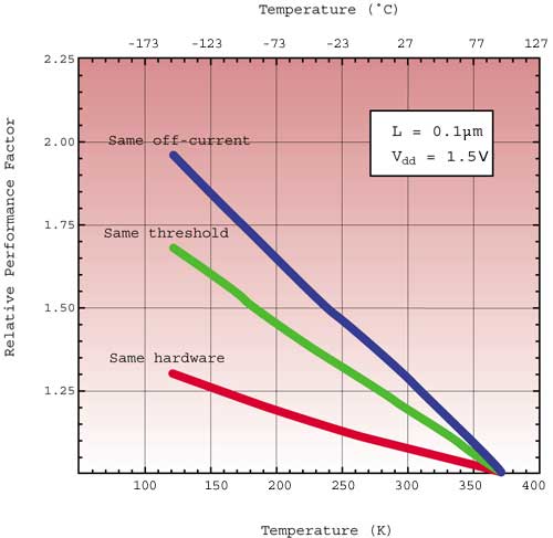
Figure 1. Relative performance factors (with respect to the 100oC value) of 1.5 volt CMOS circuits as a function of temperature. Threshold voltages are adjusted differently with temperature in each of the three scenarios shown (adapted from Taur and Nowak [3]).To get a feel of how much improvement is realized with decreasing temperature, Figure 1 shows the performance of a 0.1m CMOS circuit (relative to the performance of a 0.1
m circuit designed to operate at 100oC) as a function of temperature [3]. The performance behavior is shown for three different assumptions about the threshold voltage. Only a slight performance gain is realized if the circuit, unchanged from its design to operate at 100oC, is taken down in temperature (same hardware). This is due to a rise in threshold voltage that partially offsets the gain due to higher mobilities. Tuning threshold voltages down, until eventually the same off-current as the 100oC circuit is achieved, yields the greatest performance gain: almost 2X at 123 K.In addition, the improvement in electrical conductivity, achieved with lowering the temperature of the two metals used today to interconnect circuits on a chip, is shown in Figure 2 [7]. A conductivity improvement of approximately 1.5X, 2X, and 10X is realized at about 200 K (-73oC), 123 K (-150oC), and 77 K (-196oC), respectively. Reduction in capacitive (RC) delays can therefore approach 2X at the lower (77 K) temperatures.
 |
Figure 2. Electrical resistivity ratio for aluminum and copper at low temperatures
(adapted from Barron [7]).
Other Low Temperature Behavior
Material Property Trends at Low Temperatures
Consideration must be given to how material properties change with decreasing temperature. The following list can be used as a general guideline for how materials commonly used in electronic packaging behave when cooled from room temperature to about 80 K [2]:
- Thermal/Mechanical Properties
– Young’s Modulus increases
– Yield strength increases
– Specific heat decreases
– Thermal conductivity of most pure metals, ceramics, and silicon increases
– Thermal conductivity of metal alloys decreases
– Coefficient of Thermal Expansion (CTE) decreases - Electrical Properties
– Electrical resistivity decreases
– Dielectric constant for printed circuit material remains nearly constant
Naturally, exceptions exist, so one must seek out reliable and accurate material data before entering into an actual design.
Reliability
The reliability of CMOS devices is a strong function of operating voltage and temperature. One would expect the relative improvement in mean-time-to-failure (MTTF) to be proportional to a temperature dependent term expressed by the Arrhenius relation [5]:
 |
where To and TR are the operating and reference temperature, respectively, k is Boltzmann’s constant, and H is a fitted parameter related to the activation energy of a given thermal process.
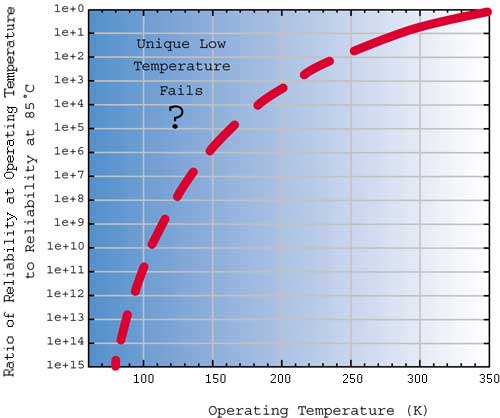
H will typically range between 0.3-1.2 eV. If a value of 0.3 eV is assumed, the relative change in MTTF can be seen graphically in Figure 3.
 |
Figure 3. CMOS device fails as a function of temperature according to Arrhenius relation.However, some recent information suggests that there are other defects that are unique to low temperature [8]. These defects, undetected at normal operating temperatures, manifested themselves as timing failures at or below 0oC due to an increase in electrical resistance at the defect. In fact, testing at low temperatures is now being used as a screen to catch silicide opens that would otherwise go undetected under normal testing but fail later in product life [9]. This new data suggests that reliability could potentially get worse as you go to lower and lower temperatures.
To compound matters, failures due to the presence of thermal strains also increase with lower and lower (sub-ambient) temperatures. Thermal strain usually results when joined materials of differing CTE undergo a change in temperature. Interconnects at all levels of packaging experience this behavior. The temperature change is usually between room temperature and normal operating temperature. As operating temperatures decrease, thermal strains become larger even though CTE is decreasing.
Thermal Design Issues
Refrigeration Selection
There are many issues that must be considered when designing an ultra-low temperature thermal management system. Choosing a refrigeration technology that is capable of removing a given heat load, at a given heat flux, while maintaining a specified temperature is a good place to start. With microprocessors expected to exceed 200 W by 2005 and high performance processors to exceed 100 W/cm2 at the chip level [10], finding a refrigerator that can do the job is a formidable challenge.
Below -40oC, the heat removal capability of standard single stage vapor compression refrigerators drops off precipitously. Two-stage vapor compression cycles have shown the potential to cool to -80oC while mixed-refrigerant Joule-Thomson refrigerators have demonstrated the potential to cool to -100oC [11]. Stirling or Gifford-McMahon refrigerators have the best shot at getting down to LN2 temperatures.
Power Consumption
The next issue to consider is the amount of power consumed by the refrigerator to provide the desired cooling. The parameter that defines the relation between the amount of cooling and the power required to provide the cooling is the coefficient of performance, or COP:
 |
Recall that the optimal performance of a refrigeration system is limited by the COP of the reversible Carnot refrigeration cycle,
 |
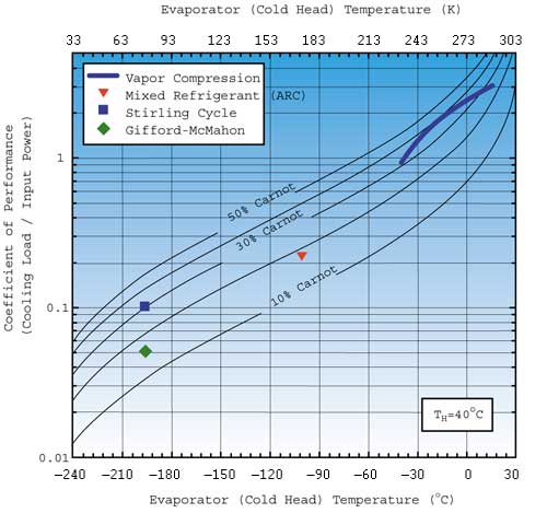
where TL, the low temperature reservoir temperature, is associated with the evaporator surface temperature, and TH, the high temperature reservoir, is associated with the condenser ambient temperature. Actual COP is often expressed as a percentage (or fraction) of Carnot COP. It is in this context that the actual COP of selected refrigeration technologies is compared to Carnot COP (Figure 4) as the evaporator decreases in temperature down to 77 K [11, 12].
 |
Figure 4. Coefficient of Performance (COP) for various refrigeration
technologies in relation to Carnot (ideal) COP.Vapor compression cycles are relatively effective operating between 30-40% of Carnot COP. Below -40oC the decrease in COP becomes more pronounced. Below 50 K COP drops off precipitously. Unquestionably, power consumption requirements for the cooling system increase dramatically as the operating temperature decreases.
Mode(s) of heat transfer
IBM and KryoTech have both chosen to attach the evaporator of the refrigeration system to the electronic module being cooled. Heat is therefore removed from the electronics by conduction to the refrigeration system.
The electronics to be cooled in the ETA10 supercomputer were submerged in a bath of LN2 (cryostat). Heat was removed from the electronics via pool boiling. At the system level, either an open system approach was used where LN2 was supplied continuously from a bulk tank that was replenished by a supplier who liquefies gases, or a closed loop approach was taken where a refrigeration system reliquified the boiled-off gas and returned it to the cryostat.
Low temperature coolants could also be circulated within a system to cool electronic equipment. Ausimont (www.ausimont.com) supplies a perfluoropolyether called GALDEN HT70 that is advertised to work as a circulating heat transfer fluid down to -80oC. DOW (www.dow.com/heattrans/index.htm) offers a silicone polymer called SYLTHERM XLT that is advertised to work down to -100oC.
Parasitic Heat Loads
Systems at low temperature are prone to heat infiltration that results solely from the difference in temperature between the system and its surroundings. This parasitic heat load on the system adds to the cooling load the refrigeration system must remove. A good thermal design minimizes this unwanted heat load. At ultra-low temperatures sophisticated insulation schemes are required. Vacuum insulation with mylar reflection sheets is typically used in cryogenic applications. Electrical feedthroughs are most difficult to insulate thermally and are often the largest source of parasitic heat into the system.
Condensation
Condensation forms on any surface with a temperature below that of the ambient dew point. It can lead to corrosive fails in printed circuit boards and can also short module I/O. Condensation formation becomes more prevalent as the operating temperature drops. Mitigating condensation at temperatures above -40oC has typically been handled with a combination of relatively simple (foam) thermal insulation and surface guard heating. At very low temperatures either more sophisticated thermal insulation is required (e.g. vacuum insulation) or active humidity control, which effectively lowers the dew point temperature, is required.
Summary
The issues that affect the operation of CMOS computers down to ultra-low temperatures (anywhere from -40oC to -196oC) have been discussed. While there might be significant electrical performance improvement by going to these temperatures, the technical issues of refrigeration selection, power consumption, mode(s) of heat transfer, parasitic heat loads, and condensation pose a significant challenge. Furthermore, it is questionable whether the reliability of the electronics will continue to improve as these low temperatures are reached.
References
1. Peeples, J. W., Little, W., Schmidt, R., and Nisenoff, M., Low Temperature Electronics Workshop, Proceedings of the Sixteenth Annual IEEE Semiconductor Thermal Measurement and Management Symposium, pp. 108-109, 2000.
2. Carlson, D. M., Sullivan, D. C., Bach, R. E., and Resnick, D. R., The ETA10 Liquid-Nitrogen-Cooled Supercomputer System, IEEE Transactions on Electronic Devices, Vol. 36, Number 8, pp. 1404-1413, August, 1989.
3. Taur, Y. and Nowak, J., “CMOS Devices Below 0.1 mm: How High Will Performance Go?,” Electron Devices Meeting, Technical Digest, International , pp. 215-218, 1997.
4. Rose, K., Mangaser, R., Mark, C., and Sayre, E., Cryogenically Cooled CMOS, Critical Reviews in Solid State and Materials Sciences, Vol. 4, Number 1, pp. 63-99, 1999.
5. Clark, W. F., Badih, E., and Pires, R., G., Low Temperature CMOS – A Brief Review, IEEE Transactions on Components, Hybrids, and Manufacturing Technology, Vol. 15, Number 3, pp. 397-404, June, 1992.
6. Krane, R. J., Jaeger, R. C., Bar-Cohen, A., and Gaensslen, F. H., MOS Electronics and Thermal Control for Cryogenically-Cooled Computer Systems, in Advances in Thermal Modeling of Electronic Components and Systems, Vol. 2, edited by Bar-Cohen, A. and Kraus, D., ASME Press, New York, pp. 185-232, 1990.
7. Barron, R. F., Cryogenic Systems, 2nd Edition, Oxford University Press, New York, 1985.
8. Needham, W., Prunty, C., and Yeoh, E. H., High Volume Microprocessor Test Escapes, an Analysis of Defects Our Tests are Missing, Proceedings of the IEEE International Test Conference, Piscataway, NJ, pp. 25-34, 1998.
9. Tseng, C. W., McCluskey, E. J., Shao, X., and Wu, D. M., Cold Delay Defect Screening, Proceedings of the 18th IEEE VLSI Test Symposium, Montreal, Quebec, Canada, pp. 183-188, 2000.
10. National Electronics Manufacturing Technology Roadmaps, National Electronics Manufacturing Initiative, Inc., Herndon, VA 20170-4214, 2001 (in print).
11. Ellsworth, M.J. Jr., Moser, E.K., Khatri, A., and Boiarski, M., Performance of a Mixed-Refrigerant System Designed for Computer Cooling, Advances in Cryogenic Engineering, Vol. 45, 2000.
12. Schwall, R.E. and Harris, W.S., Packaging and Cooling of Low Temperature Electronics” Advances in Cryogenic Engineering, Plenum Press, NY, pp. 587-596, 1991.


