The naphthalene sublimation technique has been demonstrated by a number of investigators to be an excellent method for obtaining heat transfer results [1,2] and a few have applied this technique to applications focused on electronic cooling [3-6]. These investigators have found that the mass transfer process can be set up with cleaner boundary conditions and can be studied more easily and more accurately than the corresponding heat transfer process.
This article focuses on the laboratory equipment, naphthalene casting, and measurement technique to obtain the transfer coefficients for electronic modules mounted to printed circuit cards. Of course, standard thermal techniques can be applied to obtain these transfer coefficients as most recently described by Molki and Faghri [7] but radiation and primarily conduction losses have to be accounted for in the final tabulation of the heat transfer results. The method to be described does not encounter these extraneous losses.
Heat/Mass Transfer Analog
The basis for using the mass transfer technique rests with the analog between heat and mass transfer processes. Dimensional analysis performed on the equations describing heat and mass transfer processes demonstrate that for any geometrically similar configuration and for similar boundary conditions equations of the same form can be obtained. The result is that a simple relation exists between the Sherwood number describing the mass transfer process and the Nusselt number describing the heat transfer process. The boundary condition for the mass transfer experiments corresponds to an isothermal surface for the analogous heat-transfer problem.
The equations necessary for computing the Sherwood number with naphthalene as the transfer substance are given by:
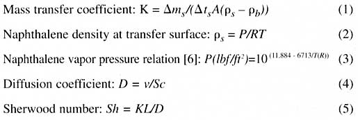 |
where:
ms = Change in mass during sublimation process
ts = Change in time during sublimation process
A = Naphthalene surface area
T = Naphthalene surface temperature
R = Gas constant of the naphthalene vapor
b = Bulk naphthalene vapor density (zero for the experiments to be described)
Sc = Schmidt number, 2.5 [8]
L = Characteristic length dimension
v = Air kinematic viscosityThe Sherwood number computed from the above equations can then be simply transformed into a Nusselt number describing the corresponding heat transfer process through the following relationship:
where Pr is the Prandtl number and for most forced convection problems n ~ 0.34. Further, the heat transfer coefficient, h, can then be easily obtained from the definition of the Nusselt number, hL/k, where k is the thermal conductivity of air.
Experimental Procedure
Before describing an actual experiment, the step-by step procedures used for the mass transfer technique can be summarized as follows:
1. Forming
The formation of an adequately smooth naphthalene surface (essential for the heat/mass transfer analogy) of the desired shape was achieved by either casting or machining (only the casting process will be described here). Naphthalene is a substance that can be easily purchased from most chemical supply houses in nearly pure crystalline form and then melted at around 80oC to permit casting.
2. Thermal Stabilization Period
As the vapor pressure of naphthalene is sensitive to temperature (about 10%/oC at room temperature – see equation 3), every precaution was taken to ensure thermal equilibrium with the temperature of the air in the laboratory room and the accurate measurement of temperature during the data run.
3. Prerun
Prior to each data run, a prerun was performed in which the naphthalene surface was installed in the test apparatus for about ten minutes at the test conditions. This was to further ensure that thermal equilibrium with the room ambient had been achieved and to blow any loose naphthalene particles off the test surface.
4. Before Run Measurements
To determine the overall mass transfer from a naphthalene surface during a data run, the formed naphthalene test piece was weighed before the run with a precision balance capable of discriminating to within 0.00001 gram.
5. Data Run
The duration of the data run was selected so that an average change in surface elevation was in the range of 0.001 to 0.003 inch. A timer with a scale division of one second was used to measure the duration time. A typical run may last 20 to 30 minutes.
6. After Run Measurements
In order to obtain the overall or local mass transferred (only overall mass transfer is described here), the measurements performed before the run (step 4) are repeated after the data run.
7. After Run Correction
A correction was applied to the differences in the before and after run measurements to account for the natural convection sublimation that occurs during the time the actual measurements are performed. This correction was determined from an auxiliary run in which all the aspects of the actual data run were repeated, but without the forced airflow present.
Experiments
A large portion of electronic packaging continues to consist of card-on-board configurations. As thermal engineers, we focus a significant amount of our time on determining the convective transfer (external thermal resistance) of the modules mounted on these cards. Early in a project development cycle, many card designs may be proposed, each needing to be thermally evaluated in a timely manner.
The one component of a module’s thermal network that is affected most by various module placements on the card is the external resistance. This resistance, once determined, can then be used in constructing a thermal nodal network model of the module leading ultimately to an estimation of chip junction temperature for various environmental conditions. Using heat transfer techniques, in which calibrated thermal modules or simulated heated blocks are employed to determine this convective resistance, can be extremely time consuming, especially when multiple module configurations on the card must be examined.
In view of these objectives, the mass transfer technique is quite attractive. The experiment to be described focuses on the convective transfer from the module exposed surfaces.
The test apparatus for measuring module surface convective transfer is shown in Figure 1. The essential components of the apparatus consist of the card test section, transition section, laminar flow element, and air moving device. Air from the laboratory room is drawn over the card through the transition section to the laminar flow element where the card air flow rate is measured. The downstream placement of the blower precluded preheating of the air, which might have occurred had the blower been upstream.
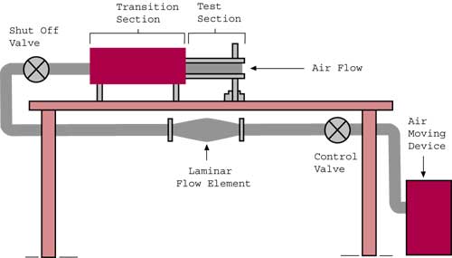 |
Figure 1. Test apparatus The card test section was designed to test modules at various locations on a card. Various card sizes can be accommodated in the test apparatus with minor modifications. The design of the test section was such that the time of installation and removal of the naphthalene test module could be minimized. Only a few screws and pressure-sensitive tape were required to seal the test section.
One of the objectives in using a naphthalene test module was to maintain the same air flow pattern over the card as in the actual case. This was accomplished by removing the module aluminum housing encasing the die and then casting naphthalene directly on the module substrate to the height of the housing. Thus, the flow pattern would not be changed in any way. In order to add a layer of naphthalene to the top of a module substrate, several casting molds were investigated. The one that proved most successful is shown in Figure 2.
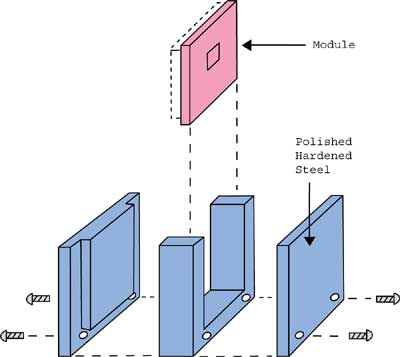 |
Figure 2. Module casting mold.The casting procedure involves several steps. The module with its housing removed is slipped into the mold so that when the pins are touching one surface of the mold a uniform gap exists above the substrate into which naphthalene is poured. To prevent naphthalene from spilling over into the region of the pins, pressure-sensitive tape was used to mask off this region.
To ensure that the mold was completely filled, excess naphthalene was poured so that some buildup occurred on the top of the mold. This excess, once solidified, was removed by melting it on the hot plate in a way similar to moving an iron across an ironing board. The tape was then removed and, by several strategic hammer blows, the module was removed from the mold.
As shown in Figure 2, the largest surface of the mold in contact with the naphthalene was fabricated of hardened steel and polished to a mirror-like finish. With the hardened steel the surface could be maintained relatively free of scratches, thereby allowing it to be easily separated from the naphthalene during the unmolding the process.
With the naphthalene test module placed in the test section, the desired flow rate over the card was set during the prerun period. During this period, with the shutoff (ball) valve completely opened, the control (gate) valve was adjusted to the desired flow rate for the test run. Following the prerun, the shutoff valve was closed and the module removed from the test section for the before run weight measurement. Once weighed, it was installed back on the card and the test section sealed.
With the blower operating, the timer was started at the same time the shutoff valve was opened. At the end of the timed run, the reverse procedure was followed and the module removed from the test section for final weighing. To avoid any contact with the naphthalene surface during the measurement phase, a pair of tweezers was used to transport the module while contacting only the module pins.
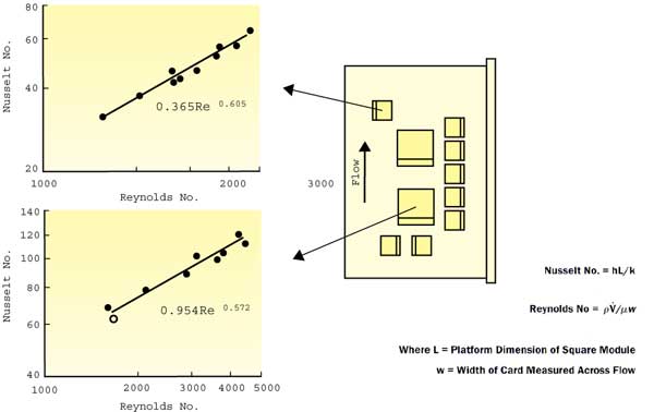 |
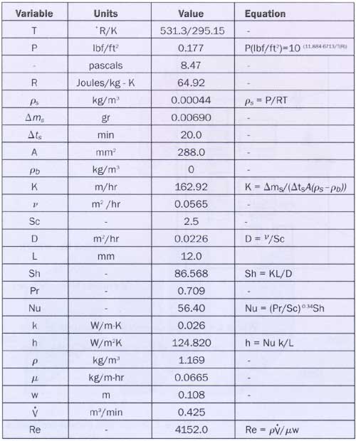
Figure 3. Module heat transfer coefficientsTypical results for both 12 mm and 28 mm modules are shown in Figure 3. In addition to these two module sizes, molds have also been fabricated for many other module sizes. A sample calculation for a test run with a 12 mm module is shown in Table 1.
In all cases the major contribution to uncertainty occurs with the naphthalene surface temperature (estimated to be within 0.5oC). Applying the root sum square of the individual uncertainties of each variable measured gave results that were estimated to be within 3%.
Summary
The mass transfer technique has been described to obtain the convective heat transfer from the surfaces of electronic modules mounted to a printed circuit card. Although not discussed here, this technique has been successfully applied to determine average convective transfer coefficients from card surfaces, finned heat sinks, and corrugated passages, as well as localized convective transfer coefficients [6].
Table 1: Sample Calculations for 12 mm Module.
 |
The advantages in the use of the mass transfer technique can be summarized as follows:
- More easily and accurately studied than the corresponding heat transfer process.
- Faster modeling of multiple hardware configurations, enabling:
– Earlier discovery of thermal design problems.
– More system control over thermal design. - No requirement for local velocity measurements.
- Ability to measure localized transfer coefficients
(not described in this article).
References
1. R. Goldstein and H. Cho, A Review of Mass Transfer Measurements Using Naphthalene Sublimation, Exp. Thermal and Fluid Science, Vol. 10, 1995, pp. 416 – 434.
2. P. Souza Mendes, The Naphthalene Sublimation Technique, Exp. Therrmal and Fluid Science, Vol. 4, 1991, pp. 510-523.
3. E.M. Sparrow, J.E. Niethhammer and A. Chaboki, Heat Transfer and Pressure Drop Characteristics of Arrays of Rectangular Modules Encountered in Electronic Equipment, Int’l. Journal of Heat and Mass Transfer, Vol. 25, No. 7, July 1982, pp. 961 – 974.
4. E.M. Sparrow, S.B. Vemuri and D.S. Kadle, Enhanced and Local Heat Transfer , Pressure Drop and Flow Visualization for Arrays of Block-like Electronic Components, Int. Journal of Heat and Mass Transfer, Vol. 26, No. 5, May 1983, pp. 689-700.
5. C.A.C. Altemani and L.L.Menegaido, Enhanced Convective Cooling of a PCB in a Duct, EEP -Vol. 10-2, Advances in Electronic Packaging, ASME 1995, pp. 817 – 822.
6. R.R.Schmidt, Local and Average Transfer Coefficients on a Vertical Surface Due to Convection from a Piezoelectric Fan, Itherm, Washington, D.C., May, 1994, pp. 41-49.
7. M. Molki andM.Faghri, Temperature of in-line Array of In-line Array of Electronic Components Simulated by Rectangular Blocks, ElectronicsCooling, May , 2000.
8. H.H. Sogin, Sublimation from Disks to Air Streams Flowing Normal to their Surfaces, Trans. Am. Soc. Mech. Engrs. 80, 1958, pp. 61-71.


