Vapor compression refrigeration is being adapted to cool computer and telecommunications equipment in a limited number of high performance applications. Vapor compression can lift large heat loads and can heat sink at below ambient temperatures. Cold plates can offset high case-to-junction temperature gradients to keep high power integrated circuits from overheating and/or can lower junction temperatures for enhanced integrated circuit performance.As a method of enhancing computer performance, below ambient cooling has been actively researched since the 1960’s. Today’s mainstream semiconductor technology, CMOS, has been repeatedly characterized at low temperatures. Multiple performance enhancing reasons exist to cool CMOS devices to very low temperatures. The challenge is to do so reliably and cost-effectively.
Although early (1960-1980) cold electronics development programs targeted 77K or lower temperatures, a moderate approach to low temperature computing has gained momentum in recent years. Vapor compression cooling technology is employed to chill components to a minimum temperature of 233K (-40oC) for two good reasons.
First, reliable, relatively inexpensive vapor compression systems can lift high heat loads at this temperature. Second, 233K presents less significant electronic packaging problems to be overcome than does operation at 77K. Vapor compression cooling technology, identical to that used in home refrigeration, is currently employed in at least two classes of commercially available computers [1].
Mechanically Assisted Cooling
High power electronic systems are testing the limits of traditional cooling methods. Effective heat removal is required to keep silicon junction temperatures below critical temperatures at which devices will fail to operate correctly. Natural convection or forced air cooling is proving to be insufficient in an increasing number of applications. Mechanically assisted cooling can meet these needs, but must do so at acceptable costs. Vapor compression cooling of specific, high performance applications can provide favorable cost/benefit ratios.
Mechanically assisted cooling subsystems are said to provide “active cooling” since they require energy. Some mechanically assisted cooling subsystems reduce the heat sink surface temperature below ambient air temperature. It is convenient to refer to a heat sink that operates at below ambient temperatures as a cold plate.
Key attributes of the cooling subsystem include its efficiency, its operating temperature and its cooling capacity. The subsystem’s efficiency can be specified as its Coefficient of Performance (COP), or the amount of heat it can move divided by the power the subsystem consumes to move that heat.
Active cooling subsystems can be designed to operate over a wide range of temperatures. Simple forced air systems operate at above ambient temperatures. Mechanically chilled fluid loops and direct evaporation vapor compression systems are useful at temperatures above approximately 210K. Cryogenic systems can be engineered to cool to liquid helium (4K) temperatures.
Large systems can be designed to lift large heat loads. However, Carnot efficiency theoretically limits COP as a function of operating temperature. Low temperature systems will not be as efficient as higher temperature systems. This results in a practical application range from fractions of a watt at 4K to hundreds of watts at 233K.
The most common cold plate technologies for high performance cooling are currently thermoelectric devices, chilled fluid loops and vapor compression refrigeration.
Thermoelectric Devices
Solid-state thermoelectric devices have no moving parts, which is far and away their most important advantage. Unfortunately, their relatively poor COP limits them to low power applications. Lower temperatures can be achieved by cascading multiple thermoelectric stages, but with a corresponding decrease in COP. Furthermore, high power applications may require additional active cooling to remove heat from the rejection side of the thermoelectric device.
Circulating Chilled Liquid System
Chilled liquids have the advantage of prior adoption. Properly designed systems move impressive heat loads, often employing water as the circulating fluid. Chilled liquid systems are ultimately limited by their working fluid. Most require a relatively high mass-flow rate and must employ a secondary refrigeration apparatus and heat exchanger to refrigerate the working fluid.
Vapor Compression
Vapor compression refrigeration offers several important advantages. These include low mass flow rate, high COP, low cold plate temperatures and the ability to transport heat away from its source. The following is a more detailed look at vapor compression refrigeration of high performance electronics.
Vapor Compression Refrigeration
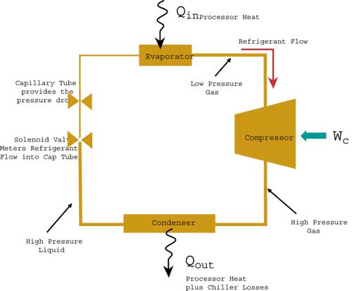
Figure 1 is a schematic representation of the vapor compression cycle. At the top of the loop, heat is introduced to the system by the device being cooled. This heat vaporizes liquid refrigerant in the evaporative cold plate. This vapor is subsequently carried through the suction tube to the compressor. Work is supplied to compress the warm vapor into a hot, high-pressure vapor that is passed to the condenser.
 |
Figure 1. Refrigeration cycle schematicThe hot high-pressure vapor releases its heat to the air stream across the condenser fins as it condenses into a warm liquid. Warm liquid is pumped from the bottom of the condenser through an expansion device where its pressure and temperature drop significantly, creating the refrigeration effect. The cycle completes as the cold fluid passes to the cold plate.
The cycle depicted in Figure 1 offers several advantages for electronic cooling applications. Vapor compression systems can reject heat far from the source by separating the evaporator and condenser in a so-called “split system”. Vapor compression refrigeration transports large quantities of heat with a small mass of circulating fluid. This is an advantage over a chilled fluid loop that requires a much higher mass flow rate of coolant.
Vapor compression operates at a COP approximately three times that of thermoelectric devices in a similar application. Vapor compression can produce -40oC cold plate temperatures using common food storage and cooling refrigerants.
Refrigerant Fluids
The refrigerant physical properties and operating pressures determine its evaporating temperature and its capacity to transport heat. A wide variety of vapor compression refrigerant fluids are commercially available. Water, alcohol, butane, and ammonia are among the list of wellstudied refrigerant fluids.
Operating pressure range, heat capacity, atmospheric disruption potential, explosion hazard and corrosion potential make some fluids inappropriate for some applications. R-134a and R-404a are common refrigerants currently in use in high power electronics cooling applications.
Heat Capacity and Heat of Vaporization
When bounded systems of gases, liquids or solids absorb heat they must either increase in temperature or change their physical state. For example, the temperature of a gram of water will increase one degree centigrade when it absorbs one calorie of heat. Similarly, at a given pressure and temperature, one gram of water will absorb nearly 540 calories of heat without temperature increase as it changes from a liquid to a gaseous state.
This characteristic amount of heat absorbed during a state change is referred to as a material’s heat of vaporization. Vapor compression refrigeration employs the refrigerating fluid’s heat of vaporization. Practically this allows a small fluid mass to transport a relatively large amount of heat.
Temperature of Vaporization
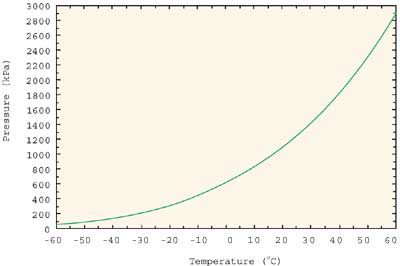
Just as water turns to steam (water vapor) at 100oC at atmospheric pressure, a given refrigerant will vaporize at a specific temperature at a given pressure. The pressure vs. temperature characteristic curve determines the lowest practical operating limit of a particular refrigerant. Figure 2 shows the pressure-temperature characteristic curves for the commercial refrigerant R-404a. Low cold plate temperatures can be used to offset the temperature rise that occurs at the interface between a cold plate and its load device or to lower the operating temperature of the load device.
 |
Figure 2. PT curve for R-404aBenefits of Sub-Ambient Cooling
CMOS technology has scaled predictably since the early 1970’s. Smaller features allow more circuit elements, such as transistors, to be interconnected on a single silicon chip. Smaller transistors switch on and off faster. As CMOS scales from generation to generation, faster and more functionally rich chips are produced.
Continued improvement in wafer and device fabrication has encouraged development of physically larger chips. Larger chips containing more transistors operating at higher frequencies dissipate more power. Large quantities of heat must be removed from the integrated circuit surface to ensure that junction temperatures remain below critical temperatures. High power chips may require below ambient cold plate temperatures to ensure that device junctions be maintained at below their critical temperatures.
Sub-ambient cooling can also allow CMOS transistors to switch on and off faster. Carrier mobility, junction leakage, sub-threshold operating characteristics and interconnect conductivity favor low temperature operation [2,3].
Vapor Compression Application Issues
Application of vapor compression to electronic cooling requires careful engineering. The cold plate must efficiently lift heat from the device being cooled. Cold surfaces cannot be allowed to collect condensate from the surrounding air. Refrigerant tubing must be incorporated into the physical design to supply and remove refrigerant. The compressor and condenser unit must be integrated into the physical design. The entire solution must be cost effective and reliable.
Cold plate design must assure efficient thermal transfer from the device being cooled to the refrigerant stream inside the cold plate. Flat and smooth interface surfaces are generally required. The cold plate is fabricated from a thermally conductive material with thin wall design to shorten the thermal path from the target to the refrigerant. The cold plate internal design optimizes heat transfer. Surface texture and refrigerant path length are increased within the limits of an acceptable pressure drop between the inlet and outlet of the evaporative cold plate.
Water, a hazard to electronic assemblies, condenses on exposed surfaces at or below dew point temperatures. This issue extends to all exposed cold area of the refrigerant path. Cold surfaces must be insulated from and sealed against moisture-laden air to avoid hazardous condensation.
Vapor compression applications are typically closed loop. Refrigerant is recirculated around the loop indefinitely. This requires that refrigerant tubing be routed within the electronic assembly to connect the evaporative cold plate to the compressor/condenser assembly. Clever design is required to minimize the impact of this particular “issue”.
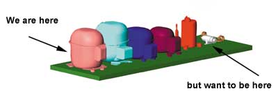
The “cooling engine” must be integrated into or otherwise accommodated in the physical design. Vapor compressors have not been designed for aesthetics. They are typically hidden in the bottom of refrigerators and water fountains. Industrial design or styling must be considered. Compressors are heavy, consume power and radiate noise. Table 1 provides size, weight and capacity information for typical modern compressors A and B along with parameters for a technically feasible but unavailable mini-compressor.
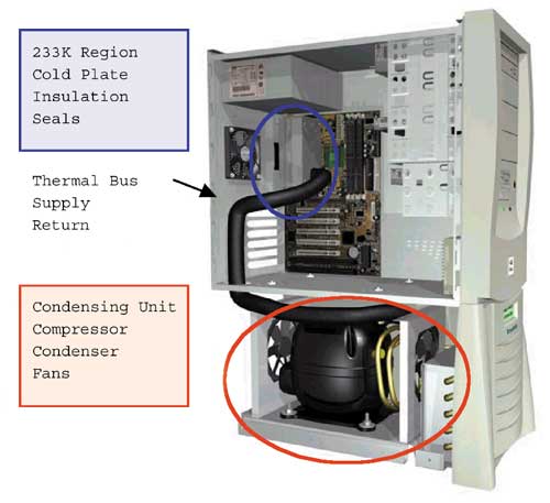
All of the application issues discussed must be considered during the physical design stage of a system if vapor compression cooling is to be effectively integrated. An example of such a system is shown in Figure 3.
 |
Figure 3. Kyrotech Super G™ Computer
Reliability at 233K
Low temperature operation results in a blend of hazards and benefits. Hazards include electro-mechanical failure due to material or thermal coefficient of expansion mismatches or electronic failure due to hot carrier effects. Only materials and components that are known to maintain their physical integrity at -40oC can be chilled.
Table 1. Specifications for Typical Compressors
 |
 |
Assembly stack-ups must be tested to insure conformity at the lowest anticipated temperature. Moisture must be blocked by seals and heating.
Semiconductor reliability -40oC is a mixed bag. Hot carrier injection (HCI) related failure rates are higher at low temperature. Device degradation due to HCI has been shown to increase at low temperatures test conditions [4,5,6] while the degrading impact of electromigration, mobile ionic contamination and dielectric breakdown decrease dramatically at low temperatures.
Conclusion
Reliable vapor compression driven cooling subsystems can be designed and manufactured for use in high performance electronic applications. Vapor compression cooling can be used for thermal management and/or performance enhancement.
Today a small fraction of all computers are equipped with vapor compression coolers. Broader use of this powerful cooling technology depends on several factors. First, the cooling technology will evolve to become a better fit for computing and telecommunication applications. Programs are underway to reduce the size and weight of vapor compressors and to build-in capacity control features that can interface seamlessly with computing. The lower temperature limit of the commodity vapor compression technology of 233K is also being addressed. Vapor compression systems are operating at much lower temperatures in the laboratory now.
Mechanically assisted cooling is emerging as a practical solution to high performance electronic cooling problems. The adoption and refinement of vapor compression cooling to address these problems can unlock a new era of electronics. One in which electronic cooling-specific compressors allow the use of ultra-high performance semiconductor devices designed specifically for low temperature operation. Microprocessor frequencies will be both scaled up and cooled up.
Acknowledgments
The author wishes to acknowledge Matthew Brown of KryoTech for his contributions and his construction of figures 2 and 3 of this paper.
References
1. Schmidt, Roger, Low Temperature Electronic Cooling, Electronics Cooling Magazine, September 2000, Vol. 6, No. 3.
2. Peeples, J. W., The Deskside Supercomputer, Advances in Cryogenic Engineering, 1998, Vol. 43a, pp 849-856.
3. Taur, Y., Device and Performance of Cooled CMOS, Commercialization of Cryoelectronics Technologies in Microelectronics, The Knowledge Foundation, Inc., February 18-19, 1999, San Francisco, CA
4. Yao, C., Tzou, J.J., Cheung, R., Chan, H., Temperature Dependence of CMOS Device Reliability, Proceedings of the 1986 IEEE International Reliability Physics Symposium, pp 175-182.
5. Nishida, T., Thompson, S.E., Oxide Field and Temperature Dependences of Gate Oxide Degradation by Substrate Hot Electron Injection, Proceedings of the 1991 IEEE International Reliability Physics Symposium, pp 310-315.
6. Wang-Ratkovic, J., Lacoe, R.C., MacWilliams, K.P., Song, M., Brown, S., Yabiku, G., New Understanding of LDD CMOS Hot-Carrier Degradation and Device Lifetime at Cryogenic Temperatures, Proceedings of the 1997 IEEE International Reliability Physics Symposium, pp. 312-319.


