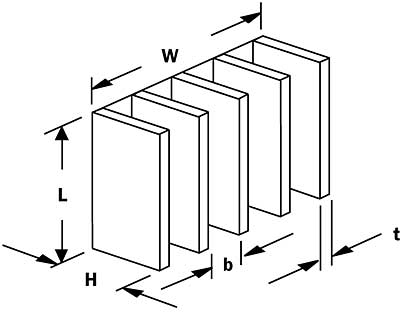
A simple formula to estimate the natural convection heat transfer coefficient on a flat plate was presented in a preceding column [1]. If, instead of a single plate, we wish to consider a closely spaced array of vertically oriented parallel flat plates, a different formula is required. The geometry to be considered appears in Figure 1 and is typical of that for a vertically mounted natural convection heat sink.
 |
Figure 1. Vertically oriented array of parallel flat plates.If the plates are spaced far enough apart, the natural convection boundary layers that develop along the surface of the plates will not interfere with each other. In this case, the heat transfer coefficients would be the same as for a single flat plate. However, if the heated plates are long enough in the natural convection flow direction (L), the boundary layers on adjacent plates will merge. As the plates are moved closer together, the natural convection heat transfer coefficient will fall below the single plate value.
Elenbaas, the first to investigate this behavior, obtained an experimental correlation to estimate the convection heat transfer coefficient under these conditions [2]. The Elenbaas correlation is of the form
 |
with the Rayleigh number, Ra, given by
 |
where
b = gap between adjacent plates
cp= specific heat at constant pressure
gc= gravitational acceleration
h = heat transfer coefficient
H= height of plate from base
k = thermal conductivity of air
L = length of plate in vertical flow direction
Nu= Nusselt number (dimensionless)
Ra= Rayleigh number (dimensionless)
Ta= temperature of ambient air
Ts= temperature of heated surface
T = temperature difference from surface to air
� = coefficient of thermal expansion for air
p = density of air
� = dynamic viscosity of air
e = 2.718, base of natural logarithmTo illustrate the application of these equations we will consider the array of plates (i.e., heat sink configuration) shown in Figure 1 with the following dimensions (all in mm): L = 100, W = 100, H = 50, t = 2. The value of b, the gap between adjacent fins, may be calculated using
 |
where W is the width of the base, Nf is the number of plates or fins, and t is the plate or fin thickness. It is also necessary to specify both the ambient air temperature, Ta , entering the array of plates and the surface temperature, Ts , of the plates. The values of air properties to be used are determined at the mean film temperature which is defined as the average of Ta and Ts . The thermophysical properties of air for use in equations 1 and 2 may be found in any basic heat transfer textbook [3].
 |
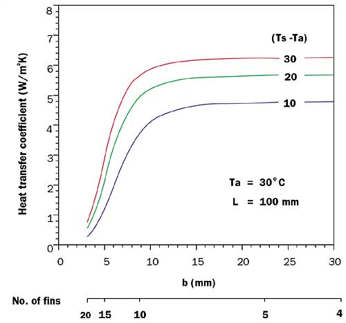
Figure 2. Natural convection heat transfer coefficients for array of plates.The values of heat transfer coefficient obtained using equation 1 for an ambient air temperature of 30oC and plate surface temperatures of 60, 50, and 40oC appear in Figure 2. As may be seen, the natural convection heat transfer coefficient increases substantially as the gap between fins increases from 3 to 15 mm, and then flattens out with further increases in gap. It may be noted that the values shown for a gap of 20 mm are within a few per cent of those obtained using a correlation for an individual vertical plate.
Of course, we are interested in the total heat transfer rate from the array of plates. This quantity depends not only on the natural convection heat transfer coefficient but also on the number of plates or fins, Nf. The total heat transfer rate is given by
 |
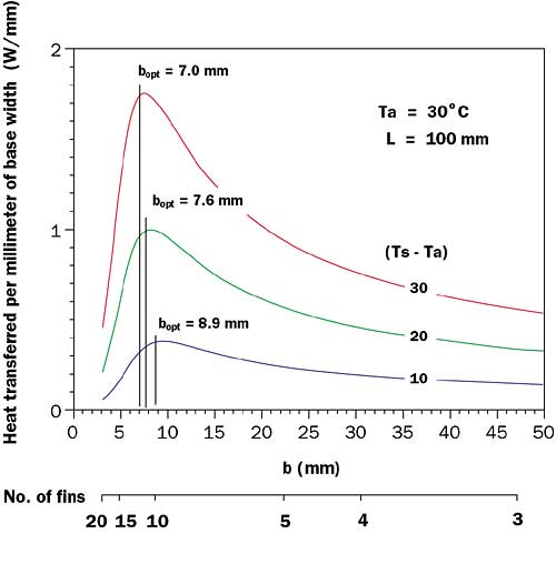
For the sake of simplicity we will use a value of 1 for fin efficiency, , in equation 1. Figure 3 shows the values of q normalized with respect to base width, W. As the value of b decreases, the number of fins or plates increases, resulting in a greater total heat transfer area. Since the value of h decreases as the value of b decreases, there will be an optimum value of b which will maximize the product of the total plate area and the heat transfer coefficient, thereby maximizing the total heat transfer rate as seen in Figure 3.
 |
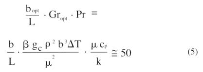
Figure 3. Total heat transfer rate per mm of heat sink base width.Elenbaas established that the optimum spacing, bopt, between the plates in air could be obtained by setting the channel Rayleigh number (based upon plate spacing b and channel aspect ratio b/L) equal to about 50, as shown in equation 5
 |
This relationship may then be used to solve for the optimum spacing bopt as given by equation 6.
 |
The vertical lines shown in Figure 3 represent the values of bopt obtained for the example calculations using equation 6.
Those readers who wish to explore this topic further are referred to reference 2 for an excellent discussion of the subject as well as additional natural convection correlations for a variety of boundary conditions.
References
- Simons, R.E., “Simplified Formula for Estimating Natural Convection Heat Transfer Coefficient on a Flat Plate,” ElectronicsCooling, Vol. 7, No. 3, August 2001, pp 12-13.
- Kraus, A.D., and Bar-Cohen, A., Design and Analysis of Heat Sinks, John Wiley and Sons, New York, NY, 1995.
- Incropera, F.P., and DeWitt, D.P., Fundamentals of Heat and Mass Transfer, John Wiley and Sons, New York, NY, 1985.


