As most readers are no doubt aware, the trend towards ever increasing processor module power is making it more and more difficult to cool directly with air. Many thermal engineers are convinced that water cooling may be the answer. This does not necessarily mean that cooling water must be supplied by the customer. Instead, in some instances it may be possible to use a water-to-air hybrid cooling scheme, which utilizes water to cool an electronic module, and then to reject the heat from the water to air via a heat exchanger. This month’s column will consider the equations necessary to estimate the module and water temperatures in such a system.
 |
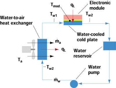
Figure 1. Water-to-air hybrid electronics cooling loop.
As shown in Figure 1, a water-to-air hybrid cooling system is comprised of a water-cooled cold plate, a water reservoir or expansion tank, a pump, and a water-to-air heat exchanger. The water-to-air heat exchanger in such a system would be similar to the finned-tube radiator found in most automobiles. The surface temperature, Tmod , of the electronic module to which the water-cooled cold plate is attached, is given by,
(1)
where qL is the module power dissipation and Tw1 is the temperature of the water entering the cold plate. Rcp is the thermal resistance of the cold plate from the attachment surface to the inlet water and includes the thermal interface resistance between the cold plate and the module.
In order to calculate Tmod it is first necessary to determine the value of Tw1. To do this we must consider the temperature rise of the water flowing through the cold plate, as well as the heat transferred from the water to the cooling air via the heat exchanger. The temperature rise of the water passing through the cold plate is given by,

where Tw2 is the temperature of the water exiting the cold plate, w is the mass flow rate of the water, and cpw is the specific heat of the water. The product of
w and cpw is equal to Cw, which is the heat capacity rate of the water. The heat transferred from the water to air is equal to the module heat load, qL, and is given by,
where Tw2 and Ta are the temperature of the water and air entering the heat exchanger, is the effectiveness of the heat exchanger, and Cmin is the smaller of the air (Ca) or water (Cw) heat capacity rates. The effectiveness is the ratio of the actual heat transfer rate of the heat exchanger to the thermodynamically limited maximum possible heat transfer rate in a heat exchanger of infinite area.
Solving for Tw2 in equation (2) and substituting the result in equation (3) results in an expression, which may be rearranged to give,
Substituting from equation (4) into equation (1) results in an expression relating the module surface temperature to heat exchanger and cold plate performance,
To illustrate the application of these equations we will consider both a range of heat exchanger performance, � Cmin, and cold plate performance, Rcp. The performance of a given heat exchanger design could be estimated based upon theory as discussed in heat transfer or heat exchanger textbooks [1, 2]. However; the usual practice is to obtain performance data from a heat exchanger vendor’s catalog or data sheets for heat exchangers that would fit within the allowable packaging volume.
 |
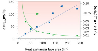
Figure 2. Effect of size on heat exchanger performance.
Figure 2 presents � Cmin data plotted vs. heat exchanger face or frontal area. The data values were obtained from vendor data available on the Internet for heat exchangers ranging in overall size (including fans) from about 15.2 x 15.2 x 10.2 cm (6 x 6 x 4 in) to 30.5 x 55.9 x 15.2 cm (12 x 22 x 6 in). As shown in Figure 2, a straight line was fitted to the data (blue squares) to obtain a linear relationship between
� Cmin and heat exchanger face area. All of the data is for a water flow rate of 0.032 liters/s (0.5 gpm) and for volumetric air flow rates varying from 0.031 m3/s (65 cfm) to 0.186 m3/s (395 cfm) for the smallest to the largest heat exchanger respectively. The air flow rates correspond to the flow rates delivered by the fans attached to each heat exchanger and result in face velocities that vary from 1.575 m/s (310 fpm) to 2.052 m/s (404 fpm). It should be noted that vendor heat exchanger data is usually presented in terms of heat load (qL ) divided by the initial temperature difference (Tw2 – Ta ) which as may be seen from Equation 3 is the same as
� Cmin. The green curve in Figure 2 is simply the reciprocal of
� Cmin and may be viewed as a thermal resistance from the inlet water to inlet air.
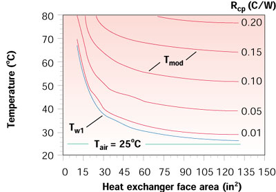
Considering a 250 W module power, an air temperature of 25oC, and water-cooled cold plate thermal resistances ranging from 0.001 to 0.2oC/W, Equations 4 and 5 are used to calculate water temperature entering the cold plate and module surface temperature as a function of heat exchanger size in terms of face area. The � Cmin values used are obtained from the linear fit in Figure 2. The results of these calculations are shown in Figure 3.
 |
Figure 3. Effects of heat exchanger size and cold plate thermal resistance on water and module temperatures for 250 W module power.
As may be seen in Figure 3, as heat exchanger size is increased the water temperature will decrease approaching the air temperature asymptotically. Of course, the water temperature can never drop as low as the air temperature regardless of how large a heat exchanger is used. As might be expected, for any specific value of cold plate thermal resistance the module temperature will also decrease with increased heat exchanger size. It might also be noted that for the values used in the example calculations there would not be much advantage gained by increasing heat exchanger size beyond a face area of 387 cm2 (60 in2) to 484 cm2 (75 in2).
References
- Incropera, F.P., and DeWitt, D.P., Fundamentals of Heat and Mass Transfer, John Wiley and Sons, New York, NY 1985
- Kays, W.M., and London, A.L., Compact Heat Exchanger, 3rd ed., McGraw-Hill, New York, NY, 1984


