The development, specification, and quality control of materials used in electronics packaging and thermal management often require the measurement of thermophysical properties.This data can be critical to a successful design, especially with the rapidly increasing cooling requirements that result from the packaging of higher performance devices. A variety of methods, involving both steady state and transient techniques, are available for measuring thermal diffusivity, specific heat, thermal conductivity and thermal resistance. In recent years the flash diffusivity method (ASTM E1461 [1]), due to its unique advantages, has seen increased use for characterizing many of the materials used in electronics packaging. Other methods commonly employed include the guarded heat flow meter, ASTM E1530 [2], guarded comparative, ASTM E1225 [3] and its modification ASTM D5470 [4], various “probe” methods based on the transient hot wire technique and the transient plane source technique.
Single Layer
The standard single layer flash diffusivity method can easily be applied to materials such as heat sinks, heat spreaders, substrates, die, molding compounds, adhesives and interface materials.
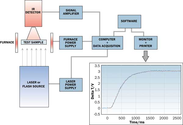
The flash method (see Figure 1) involves rapidly heating one surface of a small disk or slab of the material with a single pulse from a laser or other flash energy source, and monitoring the arrival of the resulting temperature disturbance as a function of time on the opposite surface.
 |
Figure 1. Schematic of flash diffusivity measurement and temperature rise curve.Sample geometry is normally a disk 6 to 25 mm diameter, or squares 6 to 25 mm on a side, with thickness ranging from 0.02 to 4 mm, depending on the thermal conductivity of the material and the equipment being used.
A graphite film approximately 5 �m thick is normally applied to the sample surfaces to increase the energy absorption and the emittance of the sample surfaces.
Normally the back face surface temperature is monitored with an infrared detector, making the measurement contactless. This is a significant advantage over other methods, especially for thin, low thermal resistance samples. Uncertainties in other methods related to the contact resistance between heating/cooling plates or probes and the sample, and to accurate measurement of surface temperature differences using contact sensors, can be essentially eliminated. Very thin samples and small thermal resistances can be accurately measured without stacking layers, allowing measurements at the application thickness.
The flash diffusivity method, originally described by W.J. Parker [5], is a transient heat flow technique primarily used to measure the thermal diffusivity of materials.Thermal diffusivity is a measure of how quickly a temperature disturbance can propagate through a material and is related to the thermal conductivity through the equation.
 |
where
= thermal diffusivity
= thermal conductivityCp = specific heat
= bulk densityThis relationship allows the thermal conductivity to be calculated from measurements of the thermal diffusivity, bulk density and specific heat.
Data analysis consists of fitting the measured back surface temperature rise to the theoretical model to determine the sample’s thermal diffusivity. For single layer samples, using the notation of Koski [6], the resulting analytical expression for the rear face temperature as a function of time is,
 |
whereQ = heat input to front face
t = time
a = sample thickness
and the radiation heat loss parameter or Biot number is
 |
where
 |
Each n in Equation 2 is found by solving the transcendental equation
 |
The finite width of the energy pulse can affect the measurement of thin and/or high diffusivity samples because the heating of the front surface can no longer be considered instantaneous relative to the time for the heat to diffuse through the sample.To include this effect in the analysis, the energy pulse width is folded into the results by convoluting Equation 2 with the pulse shape. If there is no heat loss, i.e., Bi = 0, and the finite pulse can be ignored, then Equation 2 leads to the Parker expression [5],
 |
where t50, the “half rise time”, is the time for the back face temperature to reach 50% of its maximum value.
Figure 1 shows an example of the back surface temperature rise measured by the IR detector. The energy pulse is initiated at time zero, there is short lag as the pulse propagates through the sample thickness, and then a steep rise followed by a more gradual rise to a plateau where the heat from the laser pulse has become equally distributed in the sample. The red curve in Figure 1 represents the theoretical temperature response (Equation 2), after matching to the detector signal, which is displayed in blue.
Specific Heat
The specific heat may be needed on its own as an input for modeling, or in order to calculate the thermal conductivity using Equation 1. For many single layer samples, the flash technique can also be used to measure the specific heat by a calibrated technique [5]. This technique involves comparing the magnitude of the sample temperature rise due to the energy pulse (final detector voltage minus baseline detector voltage) to that of a calibration sample of known specific heat, tested under the same conditions.Following the calibration run, the specific heat and thermal diffusivity of the test sample can be measured in a single run.
The specific heat of a material is defined as the amount of energy required to raise a unit mass of material by one unit of temperature at constant pressure,
 |
where
m=mass
T =change in temperatureAssuming that the pulse energy and its coupling to the sample remain essentially unchanged between the calibration and unknown samples,
and the unknown sample specific heat is calculated from
 |
where
V = change in detector voltage (proportional to
T)G = detector amplifier gain
The absorptive efficiency of the front surface of the samples to the energy pulse and the radiative efficiency of the back surface to the IR detector are controlled by coating the calibration and test samples with the same graphite film.
Specific heat can also be measured by differential scanning calorimetry, ASTM E1269 [7], usually requiring a separate, smaller diameter sample.
Multi-Layer
The thermal resistance and effective thermal conductivity of the thin interfaces and adhesive bondlines between various packaging surfaces can be easily measured by flash diffusivity utilizing a three layer, or “sandwich”, sample configuration and analysis [8].The term effective thermal conductivity is used to indicate that the contact resistances at each interface are included.
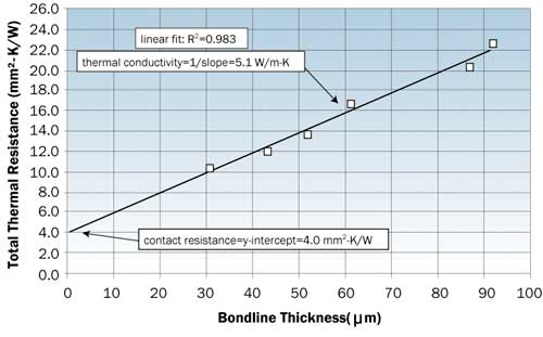
Usually the substrate samples are chosen to represent the materials and surface condition (surface finish, plating) of the surfaces, and machined to a standard sample geometry before the sandwich specimen is bonded. For a given adhesive or interface material and set of substrates, if the bondline thickness of a group of samples can be varied over a wide enough range, the measured total bondline resistance can be plotted as a function of bondline thickness. A linear least squares fit of the data results in a y-axis intercept equal to total contact resistance for the set of conditions (sum of both interfaces), and the reciprocal of the slope gives the thermal conductivity of the material. Figure 2 gives an example of data generated with silicon and copper-tungsten substrates and a high thermal conductivity grease.
 |
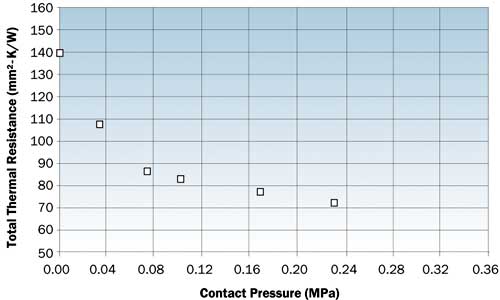
Figure 2. Total resistance vs. bondline thickness for Si-grease-CuW sandwich sample.Bare joints, as well as interface materials under a load, can also be measured with the use of an appropriate fixture. This allows measurements of the thermal resistance of interface materials as a function of contact pressure. Figure 3 gives an example of data generated with polished 6061-T6 aluminum substrates and a filled elastomer interface pad.
 |
Figure 3. Total resistance vs. contact pressure for Al-pad-Al sandwich sample.This method can be applied to the determination of the thermal diffusivity, thermal conductivity and thermal resistance of an unknown layer in a multi-layer structure, provided that the thermal properties and thickness of the other layer or layers are known or can be measured independently. We have used the approach of T.R. Lee [9] for three layer samples. In this case, the bondline represents the middle layer and the contact thermal resistances are lumped in the middle layer effective thermal diffusivity (and conductivity). Data analysis consists of fitting the measured temperature rise data to the theoretical model to determine the value of effective diffusivity for the bondline layer, with inputs of the measured t50 and the thickness, diffusivity, density and specific heat of the substrate layers.
In-Plane
Some materials used in heat sinks, heat spreaders or other areas of the package may be anisotropic in the thermal conductivity. In some composites, for example, the orientation of graphite or carbon fibers may result in a thermal diffusivity and thermal conductivity higher by a factor of two or more in the direction of the fibers compared to the direction across the fibers. In many cases, this property is desirable in order to move heat in a particular direction, or to reduce the maximum temperature at a “hot spot” by spreading heat laterally.
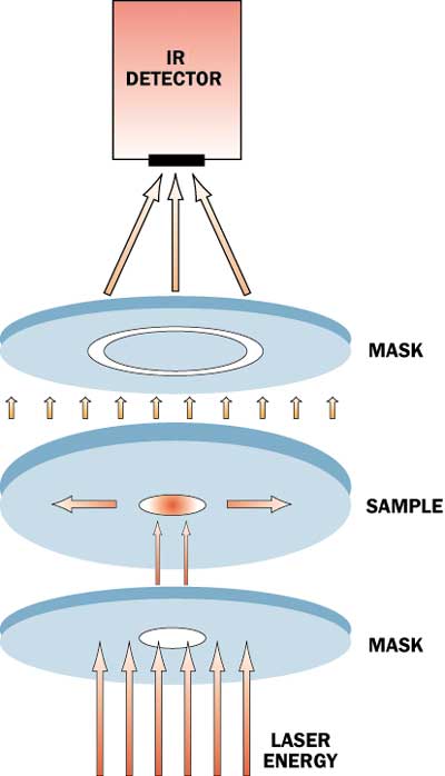
For materials that are isotropic in the plane, but have a different through-plane diffusivity, we have employed a modification of the standard flash method to measure the in-plane, or radial, thermal diffusivity. This method employs a mask to collimate the laser beam and heat an approximately 5 mm diameter spot on the front face of a 25 mm diameter disk (see Figure 4). This allows heat to flow through the thickness of the sample and spread out in the plane. Another mask is employed on the opposite face to define an annulus of approximately 8 to 10 mm in diameter that is exposed to the IR detector.
 |
Figure 4. Schematic of radial or in-plane diffusivity measurement.The temperature rise measured at this annulus is fit to a two-dimensional model [10],[11],[12] with inputs of the through-plane thermal diffusivity, sample thickness and heating and viewing diameters to determine the in-plane thermal diffusivity. This method requires a sample thickness of approximately 1 mm or less in order to maintain adequate sensitivity.
For materials that are significantly thicker than 1 mm and where it is not desirable to machine the thickness down to 1 mm, or for materials that are anisotropic in the plane, an alternate method is used to measure the in-plane diffusivity. If the material thickness is not large enough to cut out a sample of a standard geometry from the direction of interest, a group of bars can be machined from the material, stacked up and held together to form a square sample such that the through-plane direction of the sample is the direction of interest, as shown in Figure 5. In this example, the diffusivity in the “x” in-plane direction of the material would be measured.
 |
Figure 5. Preparation of assembly of bars for “x” direction in-plane diffusivity measurement.
Summary
- The flash diffusivity method has some unique advantages in the measurement of thermophysical property data such as thermal diffusivity, specific heat and thermal conductivity for many of the materials used in electronics packaging.
- Thermal diffusivity of materials such as heat sinks, heat spreaders, substrates, die, molding compounds, adhesives and interface materials can be measured with the standard single layer technique.
- Specific heat measurements of most of these materials are also possible using the flash diffusivity or differential scanning calorimetry methods, which allows calculation of the thermal conductivity.
- The multi-layer method can be applied to accurately measure the thermal resistance and effective thermal conductivity of the thin interfaces and adhesive bondlines between various packaging surfaces.
- Anisotropic materials can be characterized by a radial heat flow modification of the standard method, or by machining a square through-plane test sample such that the in-plane direction of interest is measured.
References
- Test Method E1461-01, “Standard Test Method for Thermal Diffusivity of Solids by the Flash Method”, American Society for Testing and Materials, Annual Book of ASTM Standards, Vol. 14.02, 2001.
- Test Method E1530-99, “Standard Test Method for Evaluating the Resistance to Thermal Transmission of Thin Specimens of Materials by the Guarded Heat Flow Meter Technique”, Annual Book of ASTM Standards, Vol. 14.02, 1999.
- Test Method E1225-99, “Standard Test Method for Thermal Conductivity of Solids by Means of the Guarded-Comparative-Longitudinal Heat Flow Technique”, Annual Book of ASTM Standards, Vol. 14.02, 1999.
- Test Method D5470-01, “Standard Test Methods for Thermal Transmission Properties of Thin Thermally Conductive Solid Electrical Insulation Materials”, Annual Book of ASTM Standards, Vol. 10.02, 2001.
- Parker, W.J., Jenkins, R.J., Butler, C.P., and Abbott, G.L., “A Flash Method of Determining Thermal Diffusivity, Heat Capacity, and Thermal Conductivity”, Journal of Applied Physics, 32 (9), 1961, pp. 1679-1684.
- Koski, J.A., “Improved Data Reduction Methods for Laser Pulse Diffusivity Determination with the Use of Minicomputers”, in Proceedings of the Eighth Symposium on Thermophysical Properties, Vol II, J.V. Sengers, Ed, The American Institute of Physics, 1981, pp. 94-103.
- Test Method E1269-01, “Standard Test Method for Determining Specific Heat Capacity by Differential Scanning Calorimetry”, Annual Book of ASTM Standards, Vol. 14.02, 2001.
- Campbell, R.C, Smith, S.E., and Dietz, R.L., “Measurements of Adhesive Bondline Effective Thermal Conductivity and Thermal Resistance Using the Laser Flash Method”, Proceedings of IEEE SEMI-THERM XV, 1999, pp. 83-97.
- Lee, T.R., Purdue University Ph.D. Thesis, “Thermal Diffusivity of Dispersed and Layered Composites”, University Microfilms International, 1977.
- Donaldson, A.B., “Two-Dimensional Thermal Attenuation of a Laser Pulse in a Solid”, Journal of the Franklin Institute, 294(4), 1972, pp. 275-281.
- Donaldson, A.B., “Radial Conduction Effects in the Pulse Method of Measuring Thermal Diffusivity”, Journal of Applied Physics, 43(10), 1972, pp. 4226-4228.
- Donaldson, A.B., and Taylor, R.E., “Thermal Diffusivity Measurement by a Radial Heat Flow Method”, Journal of Applied Physics, 46(10), 1975, pp. 4584-45.


