The heat flow across a metal/interstitial elastic-layer/metal joint is a very important problem in many microelectronic applications. It is generally known that when two surfaces are brought together, intimate solid-to-solid contact occurs only at discrete parts of the interface. Therefore, the actual contact area of pressed surfaces represents a very small fraction of the nominal contact surface. Even with high compressive load and optically smooth surfaces (considered ideal surfaces), the series of randomly shaped peaks and valleys reduces the actual contact area of the solids that have been brought into contact.
Thermal contact resistance at numerous interfaces introduces a significant contribution to the total thermal resistance, especially in the field of thermal management of complex, high thermal dissipating packages. The interfaces formed between contacting surfaces can play a major role in the determination of the thermal network established between the source and the sink. This is true in a variety of cases ranging from nuclear to aerospace applications to a host of configurations found in microelectronic hardware. In many instances, the phenomenon of contact resistance at the interface must be well understood in order to reduce this resistance. This is especially true if different types of interstitial materials are introduced to reduce the resistance of heat flow through a solid-to-solid interface. To this end, metallic foils, greases, elastomers, adhesive tapes, and more recently, phase-change materials are added to the joint to enhance the thermal conductive path between contacting surfaces, and, in turn, to reduce the joint resistance.
Whenever there is steady heat flow across two rough surfaces under an applied pressure, the temperature drop is observed to be proportional to the applied interface pressure. The joint temperature drop Tj is related to the heat transfer rate Qj through the joint resistance Rj or the joint conductance hj by the relationships:
 |
and
where Aa is the apparent contact area. For most contact problems, the real area of contact Ac is much smaller than the apparent contact area, i.e., Ac/Aa < 2%. Therefore, the effective gap area is approximately equal to the apparent area: Ag Aa. The specific joint resistance and joint conductance may be related as
 |
where a specific joint resistance can be introduced as
 |
which has been sometimes called the thermal impedance.
The main objective of this article is to introduce a joint conductance model for conforming rough surfaces by the mechanical contact of a compliant thermal interstitial material, i.e., graphite, under light and moderate apparent pressures. The gaps are filled with air or phase-change material, which can be characterized by its thermal conductivity. The presence of a gas or phase-change material at the interface provides a second avenue for heat flow for an interstitial material, i.e., versus a vacuum environment. The second objective is to compare the model predictions against thermal joint resistance data recently gathered, and to compute the relative error between the two. At the present, joint conductance models have only been investigated for a limited number of materials under vacuum conditions.
Review of Published Literature
The first original work conducted for metal/polymer joints was performed by Miller and Fletcher [1] and Fletcher and Cerza [2]. The authors concluded that thermal conductance values of tested elastomers were lower than the thermal conductance of bare aluminum interfaces. However, they also observed that the addition of fillers, whether metallic or non-metallic, produced higher thermal conductance value improvements than unfilled elastomers.
Rauch [3] conducted an experimental study of phase-change interface materials where compounds with and without a supporting system, such as an aluminum foil or a polyamide film, were examined. The nominal melting temperature for these materials was in the range of 51 to 60oC. The author ascertained complete wetting at the interface surfaces with the observation that the thermal resistance was zero at zero thickness, thus eliminating contact resistance. This assured that the overall thermal joint resistance would be only a function of the support thickness t and its thermal conductivity k of the phase-change wetting material.
Fuller and Marotta [4] developed an analytical model for the prediction of thermal joint conductance for both thermoplastic and elastomeric polymers placed between metallic solids. The assumptions included nominally flat contacting surfaces, uniform pressure distribution at the interface, elastic deformation of the polymer layer and asperities, and a vacuum environment. The analytical model developed employed the Greenwood and Williamson [5] definition for the elastic contact hardness to define a new polymer elastic hardness:
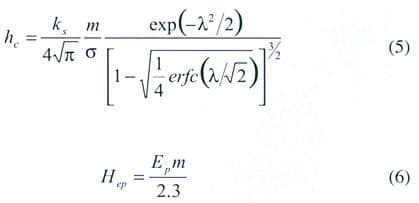 |
From the analytical model, Eq. (5), and polymer elastic hardness, Eq. (6), the authors were able to obtain a simple correlation for the dimensionless microscopic contact conductance:
 |
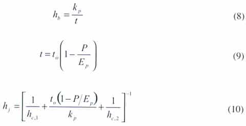
By defining the final thickness in terms of the strain, and the bulk thermal conductance with respect to the polymer thickness t and thermal conductivity kp, the authors obtained a final expression for the joint conductance defined as
 |
The applicability of analytical models to the prediction of joint conductance, and comparison to experimental data, still is quite limited. This article investigates the effect on thermal joint conductance for a solid to interstitial layer joint caused by the variation of interface pressure. This investigation was conducted for a particular interstitial layer that has shown great potential to greatly enhance conductance for an atmospheric or gaseous environment. The presence of a gas at the interface provides a second avenue for heat flow through the interface for an uncoated interstitial material (i.e., versus a vacuum environment). The experimental data were compared to an analytical model for elastic interstitial layers with and without a phase change compound coated on its surfaces.
Joint Conductance Model for Conforming Rough Surfaces
The thermal joint resistance or conductance of a joint formed by two nominally, flat rough surface depends on several geometric, physical, and thermophysical properties. Figures 1a and 1b schematically show the joint thermal resistance with a thermal interstitial material (TIM) introduced at the interface of two solids.
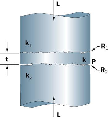 |
Figure 1a
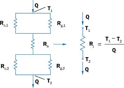 |
Figure 1b.The resistance and conductance relations are obtained from models that are based on the following simplifying assumptions:
- Nominally flat, rough surfaces with gaussian asperity height distributions
- Random distribution of surface asperities over the apparent area
- Elastic deformation of the contacting asperities and bulk layer
- Homogeneous properties for the interstitial material in the layer thickness direction
The joint thermal resistance to heat flow that incorporates the bulk properties of the interstitial layer can be defined as
 |
where Rc,1, Rc,2, Rg,1 and Rg,2 are the thermal contact resistances and the thermal gap resistances at each interface, respectively, and Rb is the thermal resistance due to the bulk properties of the layer.
The thermal contact, gap, and bulk conductance can be written as
 |
 |
 |
Therefore, the thermal joint resistance can be rewritten in terms of thermal conductance as
 |
Expressions 7-9 can be employed for the calculation of the contact conductance hc and bulk conductance hb for equation (15). The gap conductance hg may be computed from gap conductance models first developed by Yovanovich et al. [6]. The model assumes that the two surfaces in contact are uniform in temperature, and the interface gap consists of many elemental flux tubes of varying thermal resistances. The integration of these tubes over the nominally contacting area gives the overall gap conductance:
 |
Negus and Yovanovich [7] proposed a correlation that incorporated a correction factor fg that modified the above expression for the integral function:
 |
A simple approximate expression for fg was derived as
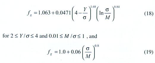 |
for 2 < Y / < 4 and 1 < M/ s <
. M is the thermal resistance resulting from the ‘rarefied gas’ phenomena in microscopically small gaps that is included in addition to the usual Fourier law based conduction. Y is the effective gap thickness, which is a function of surface roughness, contact pressure, and the elastic properties or the microhardness depending on the asperity deformation.For phase change materials or other types of filler materials present within the gap, instead of a gas, the overall gap conductance becomes:
 |
The mean plane separation Y or gap parameter is the distance between the mean planes passing through the two rough surfaces. This parameter is related to the effective RMS surface roughness and asperity slope, contact pressure, and the interstitial material Young’s modulus via the expression developed for elastomeric materials:
 |
These relations for joint conductance were compared against recently gathered experimental data for several compliant graphite materials.
Model and Experimental Data Comparisons
The joint model proposed was compared against recently gathered experimental data for graphite materials for enhancing the joint conductance for many microelectronic applications, as well as other non-microelectronic utilization. The joint conductance data are shown plotted against the joint apparent pressure in Figures 2 and 3. The joint resistance ranged from 70 to 10 mm2C/W for the apparent pressure range of 35 to 1034 kPa. The data points clearly show that the joint resistance increases with respect to increased material thickness, and that the apparent interface has a significant influence on thermal joint conductance. The trend of both the experimental data and model predictions shows that at light interface pressures, the thermal path that dominates the overall joint resistance stems from the gap resistance. While this is true at light interface pressure, at moderate to high interface pressures, the bulk resistance becomes the dominant mechanism. In general, both the experimental data and model predictions show the same trend as the data as plotted against interface pressure.
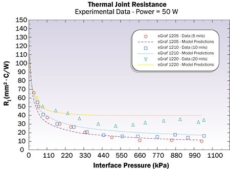 |
Figure 2. Thermal joint resistance as a function of interface pressure for various graphite material thicknesses.
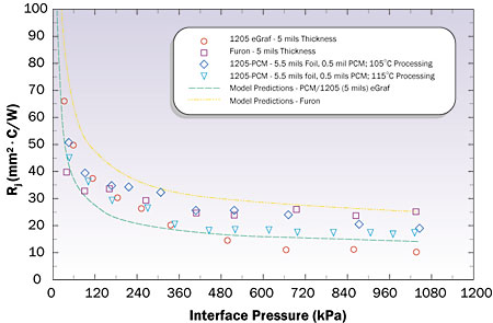 |
Figure 3. Thermal joint resistance as a function of apparent interface pressure for a PCM/graphite composite..For the phase change compound, the model predictions are below the experimental data, which is what one would expect since it incorporates many simplifying assumptions, i.e., complete wetting of the surfaces. These assumptions would make it an ideal case, thus a lower bound or best-case performance would be realized. However, for one particular graphite material, i.e., Furon, the experimental data at low interface pressures seem to be higher than the model predictions, which must indicate a thermophysical or mechanical property that is not well understood, i.e., Ei. A comparison between the experimentally measured joint resistance values and the analytical predictions appears in Tables 1 and 2. In addition, geometric and thermophysical properties for each graphite material, which was employed in the present investigation, are shown. The comparison was performed at 172 kPa since this is one interface pressure employed in many microelectronic applications. The experimental data and model predictions for the materials employed are quite good when one considers that the uncertainty for these types of measurements are quite large, i.e., typically 10 to 20%. However, what is more important is the fact that the model can predict the trend of the experimental data and distinguish the regimes of importance, i.e., gap versus bulk resistance.
Table 1. Comparison of Predicted Versus Experimental Data at 172.3 kPa
|
Table 2. Geometric and Thermophysical Data
|
Summary and Conclusions
A model has been proposed to predict the joint conductance and joint resistance for conforming rough surfaces whose contacting asperities and interstitial layer undergo elastic deformation. The model was obtained from the general, more complex model that can be used for a wide range of pressures where heat transfer can occur across the joint at both micro-contacts and gaps because of surface roughness effects.
Since the proposed model was based on nominally flat, rough surfaces, these predicted values might be used to predict a lower bound on the joint resistance for non-flat surface profiles. Further testing is required to validate the proposed model for interface pressure greater than 1034 kPa and other thermal interstitial materials with compositions different than compliant graphite materials.
 |
References
- Miller, R.G. and Fletcher, L.S., “Thermal Conductance of Gasket Materials for Spacecraft Joints,” AIAA Paper 73-119, AIAA 11th Aerospace Sciences Meeting, Washington, D.C., Jan. 10-12, 1973.
- Fletcher, L.S. and Cerza, M.R., “Thermal Conductance and Thermal Conductivity of Selected Polyethylene Materials,” AIAA Paper 75-187, AIAA 13th Aerospace Science Meeting, CA, 1975.
- Rauch, B., “Understanding the Performance Characteristics of Phase-Change Thermal Interface Materials,” Proc. of ITherm 2000, Vol. 1, May 23-26, 2000, pp. 42-47.
- Fuller, J.J. and Marotta, E.E., “Thermal Contact Conductance of Metal/Polymer Joints: An Analytical and Experimental Investigation,” Journal of Thermophysics and Heat Transfer, Vol. 15, No. 2, 2001, pp. 228-238.


