Thermal design engineers working in defense electronics are facing many challenges, some of which have been around for a long time and some that are more recent. Worldwide climatic extreme temperatures are reasonably constant and there are many military electronic systems that function in these extremes. As a result, there is significant design history available for consideration, and part of the challenge is understanding why things were done that way in the past.
Frequently, thermal management of these existing systems is based on a customized design. The more recent challenge for the thermal engineer is to move away from custom designed thermal control systems and utilize the many advances in thermal management coming from the commercial electronics field. While the cost advantages of using commercial advances are evident, the difficulty usually lies in meeting the demanding military requirements of high packaging density, low mass, long service life, and operation in harsh environments.
An additional thermal challenge over the past few years has been designing cooling concepts for commercial-off-the-shelf (COTS) electronics, which have lower maximum temperature ratings than MIL-SPEC devices. Device packaging is also different with COTS parts, which can make integration difficult. Conduction cooling of circuit boards is common in military electronics.
Circuit boards in missiles are typically attached on one side to an aluminum structure resulting in a conduction path through the board. Many avionic-based electronic boards are conduction cooled using a thermal path parallel to the plane of the board and air or liquid heat exchangers along two edges of the boards. Board cooling schemes that primarily rely on conduction need to use components packaged in a cavity up fashion in order to thermally couple the die to the board. Many commercial parts are now only available in a cavity down package because thermal management is accomplished with an air-cooled heat sink mounted to the package lid. Applying commercial advances in cooling technologies to military systems is desirable, but often not possible because of the packaging constraints.
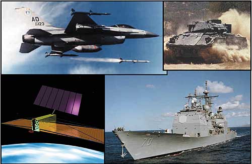
It should be noted that the term “defense electronics” is loosely defined. In this article, the term refers to electronic systems designed primarily to meet the requirements of the United States Department of Defense. Each particular system has unique aspects to its environment. Figure 1 shows four potential design environments for defense electronics and each environment poses unique thermal challenges.
 |
Figure 1. Diverse thermal environments for defense electronics.
Thermal management systems for aircraft and satellites must be as light as possible. Thermal control in the naval environment must be compatible with corrosive aspects and potentially high dissipated-heat loads. Dust in the air limits the ability to blow ambient air across the electronics. Designing thermal management systems for this wide range of requirements provides plenty of interesting work for thermal engineers.
Recent History
Only a short time ago, many defense electronics were designed with the philosophy of “this is what is required to perform the function.” The cost of these systems was secondary, except that later design activities would investigate lower cost options with the expected savings justifying the design effort.
A particular missile designed in the late 1970’s had a diode-action heat-pipe that was required to reject the electronics waste heat over long periods of operation and then to protect the electronics during periods of aerodynamic heating. This particular heat pipe was expensive and was eventually designed-out of the system. The designing-out process involved negotiations in the operating environment from the customer side and electronics improvements from the supplier side. It would have been cheaper to understand the performance versus cost evaluation earlier in the design cycle and avoid the redesign effort.
The more recent design philosophy for defense electronics has been “What functionality may be obtained for a particular cost?” One of the reasons for this change has been the rapid change in semiconductor capability. The military found that many of the high performance systems built in the 1980’s were out of date much quicker than anticipated. Design-to-cost is now required of all defense electronic designers, even thermal engineers, and commercial parts and assembly methods are used whenever possible.
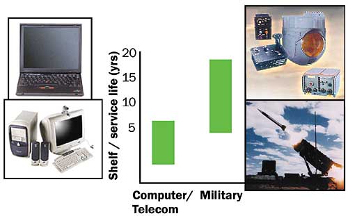
Semiconductor manufactures have historically qualified parts to standards, such as maximum temperature, and the military had significant influence in developing those standards. The semiconductor manufacturers are moving towards a use-based methodology for designing their parts where the targeted use and environment dictate the required reliability and performance. Figure 2 shows some of the differences in design environments between the commercial and military markets. The computer electronics on the left are probably only expected to last a few years and mostly operate in a conditioned air environment. The defense products on the right are required to operate for many years in harsh environments.
 |
Figure 2. Commercial and military service life.
Problems (challenges) for thermal engineers in the defense industry will increase because the junction temperatures will need to be at or below the temperatures that would exist in the intended commercial market. Maximum case temperatures for some commercial parts such as the Intel Pentium4 processor are in the 70oC range [1]. Many defense electronics systems are required to operate during and after exposure to ambient temperatures up to 70oC. If the electronics were already 70oC when turned on, it would be quite a feat to keep them from changing temperature.
Manufacturer specified temperature limits represent some combination of performance and reliability concerns, both of which degrade with increasing temperatures. From a reliability standpoint, designing for extended life compounds the problems, and it may be unreasonable to expect 15 to 20 year lifetimes from semiconductors designed for the computer and communications segments.
Numerical simulation of the thermal performance of military electronics is common and frequently required by contract. Several widely used thermal simulation tools can trace their origins to the defense industry [2,3]. Given the inherent uncertainty with simulation, some provision for design margin is required, and even specified for some spacecraft electronics [4]. The improvements in simulation capability, especially in the computational fluid dynamics field, allow designing closer to thermal limits. However, the reduced temperature limits of COTs parts may offset or exceed the benefits of smaller thermal design margins.
Example of Current Thermal Challenges
Besides the usual challenge of obtaining good information on dissipated power and appropriate boundary conditions, many of the current challenges to thermal engineers working with defense electronics can be categorized as either compromise for cost or technical challenges to removing heat. Thermal management of phased array radars serves as a good example of both challenges.
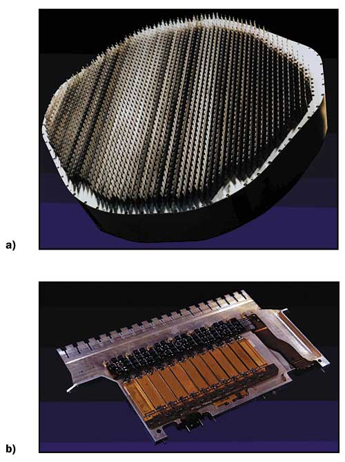
An airborne phased array radar antenna is shown in Figure 3a. Beam pointing of the radar is accomplished by individual control of many microwave modules with each module having transmit and receive circuitry. In this particular design, the microwave modules are attached to liquid cooled slats, with the slats spaced about 2 cm apart for operation at X-band frequencies.
 |
Figure 3. Phased array radar antenna and slat.
Figure 3b shows a row of microwave modules (the rectangular packages) on one slat. Most of the heat dissipation occurs in the output stage of one or more power amplifiers within the microwave modules. Currently, the amplifiers are gallium arsenide (GaAs) semiconductors but future high power amplifiers are likely gallium nitride (GaN) semiconductors. Dissipated heat loads in each GaAs amplifier may be in the tens of watts range.
Controlling temperatures is critical to the performance of the radar. The electrical performance of the power amplifiers decreases with increasing temperature and the junction temperatures of the amplifiers must be below about 150oC for reliability considerations. Electrical performance of the radar also requires that the temperature variation from module to module not exceed approximately 10oC. The slats also contain silicon devices for voltage control and logic functions and their junction temperatures must be low enough to ensure reliable operation.
Designing a system to minimize both the temperature variation and the temperature rise between the liquid coolant and electronics junctions is technically challenging. The slats are constructed of vacuum brazed aluminum skins on a core of high-density finstock. The fluid routing is critical to the temperature gradient predictions because in most airborne applications, the available coolant flow rate is such that the system dissipation heats the coolant about 15oC.
The total temperature rise from the coolant to the GaAs amplifier junctions is relatively large, with a significant percentage of the rise coming from material interfaces. Note that the heat flux levels at the power amplifier level are on the order of 100 W/cm2 for upright mounted die. High thermal conductivity materials are used where possible to minimize the peak heat-flux at the thermal interfaces.
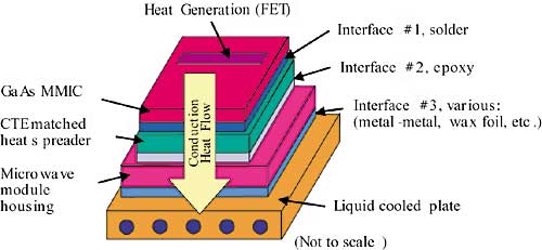
Heat generated in the amplifiers travels through several materials before reaching the liquid coolant. The materials and interfaces between the GaAs FET junction and the liquid coolant are shown in Figure 4 and typical temperature differences through the materials and interfaces are listed in Table 1.
Table 1. Typical Temperature Difference from Junction to Coolant
for Phased Array Radars at 100% Duty Cycle.
|
 |
Figure 4. Heat flow path from FET to liquid coolant.
A typical coolant inlet temperature is 20oC for airborne applications, and providing this temperature requires a refrigeration system in hot environments. Reducing the total temperature difference is a technical challenge but also illustrates the thermal compromises for cost. The largest temperature rise is in the GaAs power amplifier because of the very localized heat generation volume. An obvious method for improving the thermal performance would be to reduce the number of material interfaces (shaded rows in Table 1) and place the coolant as close as possible to the device junctions. The multiple interfaces are a result of cost and assembly concerns.
If the entire radar could be built without any defects or the need to repair it, some of the interfaces could be eliminated. At the microwave module level, the amplifiers require a hermetic environment that makes packaging expensive (The RF-energy absorption characteristic of water is useful for cooking with microwaves ovens, but detrimental to microwave module performance). Along with the cost of the packaging, it is difficult to thoroughly test power amplifiers prior to building the module, and these reasons require including rework considerations in the design.
Soldering the amplifiers to a heat spreader and then attaching the heat spreader to the module floor with epoxy allows power amplifiers to be replaced without damaging other components. If the amplifiers were soldered directly to the module floor, repairs would require heating the entire module to the solder melting temperature and possibly damage other components. In short, the need to assemble and test sub-systems as the radar is built requires several interfaces. The thermal engineer is required to compromise from an ideal thermal solution and work towards a mutually agreeable design from several disciplines.
As higher power GaN amplifiers become available, the thermal management schemes in phased array radars will be required to change. GaN amplifiers currently operate at power levels six times that of GaAs with some measurements at 10 times the power level. This power level will require the use of milli/micro-channel heat exchangers or two-phase flow and fewer interfaces between the coolant and amplifiers.
Summary
While there are many exciting technical challenges to thermal management in defense electronics, the solutions must be of reasonable cost. This drive towards lower cost can be partially met with the use of commercially produced components and systems. However, it is imperative to remember the differences in design environments between commercial applications and defense systems. Commercial electronics are usually designed for lifetimes that are shorter than defense applications and the same may be true of some thermal management products designed for the commercial market. As system costs are reduced by using components without the margin of safety that exists with Mil-Spec components, the need for accurate thermal simulation becomes even greater.
References
- Pentium 4 data sheets, Intel Corporation.
- www.crtech.com
- www.harvardthermal.com
- Mil-Std-1540B (USAF) Test Requirements for Space Vehicles.


