Thermal design in the consumer electronics business is about dealing with two difficult challenges: The first is to fulfill, and if possible surpass, customer expectations. The second is to do this in ever shortening design cycles.
After a main initial use of flat displays as computer monitors, larger flat display screens are now emerging for video purposes: the Flat TV. Market demands for the Flat TV translate into stringent cooling requirements: Consumers want a flat, slim design with high light output, mounted flat to the wall. Furthermore, fan cooling is not allowed for reasons of noise and product reliability.
This article describes a systematic approach to meet the technical and the time challenges, illustrated by the example of the thermal design process of a Flat TV monitor. The approach is based on thermal risk assessment on the system, module and component level, which are performed during different phases in the product development process. Early identification of risks and early action on perceived risks are seen as vital to keep to the strict time-to-market demands.
(Pre) Architecture Phase: System Risk Assessment
System risk assessment is based on a thermal, energy density based figure of merit (FOM). This FOM is compared to similar data over a representative population of consumer electronics devices. Developed in-house, this method has shown a consistent distribution of the FOM over the past years. The value of the FOM turns out to be related to the type of cooling of the product. The risk assessment method exploits this relation on the following principle. If consumer electronics devices in the market are observed to deploy a certain cooling technology above a certain value of the energy density FOM, then a system not deploying that cooling technology at that value is a development risk, and very likely will need alternative cooling solutions.
The proposed monitor has a much higher energy density than its predecessor. Comparing it to other natural convection cooled consumer products confirms that the high energy density poses a serious thermal challenge, as shown in Figure 1.
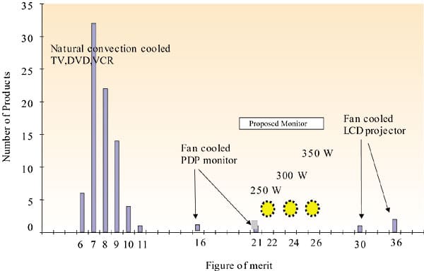 |
Figure 1. Distribution of energy density figure of merit.The distribution in Figure 1 shows that all natural convection cooled products in the company consumer electronics portfolio at that time had an FOM less than 12. The proposed monitor showed a much larger value, and much above its predecessors, actually in the region dominated by fan cooling.
The systems thermal risk assessment gives a clear power dissipation target in the architecture phase. Furthermore it shows that conventional “no-cost” cooling solutions are not likely to result in a fan-less monitor.
Architecture Phase: Module Risk Assessment
Rough CFD simulations were performed to assess the thermal feasibility of various architectures. In these studies, the system is modeled up to the module level, and the resulting temperatures are judged for associated thermal risks on the module level. To do this, the calculated temperatures are compared to thermal limit values. Limits are given by thermal requirements for functionality, safety or reliability (lifetime), and are obtained from in-house experience, international standards, or supplier information.
The difference between the calculated module temperature and the temperature limit, the so-called temperature margin, is used as an indicator for thermal risk. This temperature margin is subdivided in four classes:
- No Risk: Large Margin
- Critical: Small Positive Margin (Calculated module temperature is below the limit, but not by much.)
- Critical Hot: Small Negative Margin (Module is some degrees over limit.)
- Much Too Hot (Calculated module temperature is much over limit.)
In judging the architecture from a thermal point of view, it is acceptable to have calculated module temperatures in the “No Risk” or in the “Critical” category. To have modules in the “Much Too Hot” category is too high a risk to take and hence not acceptable. Usually, such modules are impossible to cool to acceptable levels in later stages of the product development.
For the Flat TV monitor, the mechanical architecture of the set is thermally unfavorable. The layout of the display module forces the power supply and the small signal board to be in the middle of the set. The connectors to the mains and to external devices cannot be on top of the set, which leaves the power supply in the top middle of the set, with the bottom of the set below the Power Supply Unit (PSU) completely blocked by the connectors. The mechanical layout is shown in Figure 2.
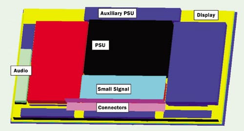 |
Figure 2. Mechanical architecture. Back cover and EMI shielding are removed for clarity.The risk score for the final architecture shows that the display module and the power supply module are in the “Critical/Critical Hot” category. This shows that fan-less cooling of this architecture is feasible, with the main risks in the display module and in the power supply. Of these, the display module is outsourced, leaving the PSU as the main thermal concern for this product development team.
Implementation Phase: Sub-Module and Components Assessment
The critical nature of the thermal design necessitates careful consideration of implementation details. As a team of mechanical designers is detailing the parts under high time-pressure, there is no way to ensure that a single thermal expert can keep the model up to date if the geometry has to be re-done. In this phase the CAD-CFD link proved vital, together with a good coordination of the thermal and the mechanical design work.
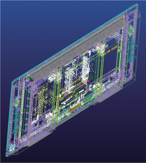 |
Figure 3. CAD model.
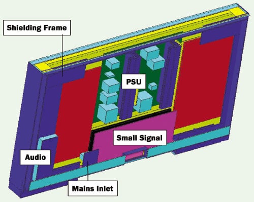 |
Figure 4. CFD model of FTV monitor.The CFD simulations used in the implementation phase are performed in more detail, especially the power supply down to the component level. Accurate power dissipations of the PSU components are unavailable at this time, so best guess values are used, and the model is updated once the first PSU board measurements are available. An example of the results of the CAD-CFD transfer is shown in Figures 3 and 4. Calculated temperature and flow fields are shown in Figure 5.
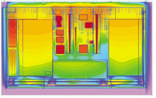 |
Figure 5. Calculated temperature and flow field of FTV monitor.Again, a risk assessment is performed on the component level for the critical module. The result of this risk assessment shows that of the thirteen components in the PSU, nine are not critical, the three heatsinks are critical, and the local board temperature at the location of the NTC (Negative Temperature Coefficient resistor) is much too hot and has a risk of solder failure. Subsequent calculations, in which the working point of the NTC was determined with greater accuracy, lead to an actual lower dissipation with corresponding lower temperatures in the NTC, and layout modifications near the NTC leads further reduced the associated thermal risk.
Testing
Extensive thermal testing was performed at the earliest possible stage. The purpose of the testing was two-fold: to validate the thermal models and to assess if the thermal behavior of the set meets the design criteria. IR measurements were performed to identify the critical components. Subsequently, thermocouple measurements were performed at critical locations.
Main issues in the testing phase are:
- Validating, checking and updating the simulation model for subsequent use in further design simulations.
- Extrapolating module measurements to final set behavior.
- Determining test conditions to evaluate the final set behavior and the set itself.
Validation and Update of the PSU Model: The PSU calculations were performed with best-guess values for the component power dissipation. The moment a PSU sample became available for measurement, the efficiency proved to be better than the worst case estimates used for the calculation. The model was updated, and a cost reduction was obtained by using smaller extrusion sinks.
Extrapolation of Test Results to Final Set Behavior: Measurements were started at the earliest possible moment, starting with bare modules. The results were extrapolated to the set behavior, first using an experience based “average temperature rise in the cabinet”, then using the difference between simulation of the bare module and the module in the system.
As the development progressed, the thermal measurement prototype became more and more like the real set. A mock-up cabinet was added, then the small signal board and the audio amplifier, and finally the real plastics and the real PSU.
This method of a test set-up (i.e., growing from a thermal mock-up to a full product and using set calculations to translate module measurement results to behavior in the final set) enabled early feedback to designers.
Final Thermal Evaluation: The quality requirement is that the set must fulfill all requirements over the entire range of the spec, including multiple worst-case conditions, hence, with different picture loads, different audio loads and different mains input voltages. Three different picture loads were needed because each picture load was associated with worst case loading of a specific group of components. The resulting set of test conditions is shown in Table 1.
|
||||||||||||||||||||
A “Design of Experiments” schedule was used to determine what load parameter was influencing what component temperature. Subsequent testing in the range of measurement conditions did not show any fundamental thermal problems. Some specific local problems occurred in multiple worst-case conditions and were subsequently resolved. Furthermore, a small set of worst-case measurements was defined, and was used to evaluate further design changes.
In the end, the thermal requirements for the set were fulfilled in all test conditions including all worst-case conditions.
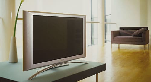 |
Figure 6. The final FTV monitor.
Conclusions
The total development of the Flat TV monitor (Figure 6) was positive. In the end, the monitor consumes less than 200 W, and is 9 cm deep. The product may be used on a tabletop stand or mounted flat to the wall. Furthermore, it is completely fan-less. Finally, product development was finished in time for the scheduled market introduction.
Cooling the monitor was not a case of identifying and eliminating a single problem cause but rather an exercise in systematic risk assessment at system, module and component level.
Enabling technologies to meet the strict timing schedule were:
- Early figure-of-merit (FOM) based system risk assessment.
- The use of CFD to identify risks, devise a solution and a backup solution, translate early module measurements to final set behavior, and to communicate with the rest of the project team.
- Transferring the geometry directly from the CAD database.
- Continuous measuring, starting as early as possible, on models of increasing complexity.
- Careful determination of measurement parameters and a measurement plan to evaluate the set behavior over the entire range of the spec.
Acknowledgments
The system cooling of complex electronics is the result of multi-disciplinary team effort. The product development of the monitor is the achievement of the entire FTV development crew, which did a great job. Apart from them, I also want to thank the members of the Cooling Competence Center for their support.
Additional Reading
- Luiten,G.A., “Cooling of a 32 inch Plasma Display Monitor”, Proceedings SEMI-THERM XVIII Conference, March, 2002, pp. 119 – 124.


