(Editor’s Note: Part 2 of this article will appear in the November 2003 issue of ElectronicsCooling.)
Cooling electronic systems is one of the major focal points of the design process and the key to a successful product launch. Many options to attain successful operation are available, ranging from passive cooling to cryogenics. These options are obviously power dissipation and heat flux dependent with many packaging, implementation and cost-of-operation issues. From a market success standpoint, the solution with the least operation and maintenance cost is the most desirable one. However, systems operation (device frequency) and packaging constraints often dictate solution alternatives that may not fit the least cost and maintenance model. Furthermore, there are many so-called “thermal limits” floating in the literature that recommend cooling based on power dissipation rather than device junction temperature. Therefore, it is the intent of this 2-part article to review commercially available cooling technologies and to cite selected examples with their salient feature as beacons for what has been and can be attained.
The Heat Dissipation Issue
Before providing a synopsis of different cooling technologies, it is best to dispel the notion of heat dissipation and the cooling technology. It is often seen that an engineer is dealing with an x-kW power dissipation system or y-W/cm2 device. Since the numbers are high, the immediate reaction is to consider a high heat flux cooling solution without any regard as to what the fundamental issue is. In electronics cooling, the primary and secondary critical metrics that a thermal engineer must meet are the device junction and solder temperatures. Whether this is a 0.5 W/cm2 device that, because of its placement on the board, has exceeded its junction temperature, or a high power processor(s), which is the engine of that system; e.g., today’s 1U blade servers with four Xenon processors. Irrespective of the system or device power dissipation, selection of the cooling solution is dictated by the junction temperature. Therefore, in the ensuing discussion, I purposefully avoid any reference to the heat removal capability of each cooling option, since the capacity is temperature and space dependent. Further, making any reference to heat removal capacity can be misleading.
When we look at the heat transport vehicles available in the market, it is quite clear that the technology is well established and extensively documented. However, a series of questions are generated when attempting to transfer this technology to electronics systems. These are:
- Would there be sufficient space to provide a large surface area for heat transfer, or to implement thermal transport (e.g., heat pipe) devices to take the heat out of the system?
- Can we use fluids with higher thermal capacitance/conductivity and subsequently higher “h” to attain the desired cooling? Would the cost of such fluids allow their implementation in the market place?
- Would the existing system packaging allow the use of a higher capacity cooling system?
- Would the market be open to a system that is mechanically much more complex and maintenance demanding than a “simple” air mover?
With these questions in mind, the cooling technology can be divided into two broad categories.
A. Passive cooling, where nature does the fluid movement (e.g., natural convection) or energy is transported by conduction and/or radiation heat transfer.
B. Active cooling, where the fluid motion is assisted by an external source, a fan in a forced air cooled system, or pump and fan of an immersion or refrigeration cooled system.
Considering the four questions that I raised, it is clear that option A is the most desired solution from the product standpoint since it has the least implementation-cost and requires, effectively, no maintenance. However, as the power dissipation increases and packaging space becomes limited (question 1), option B begins to take hold and becomes the method of choice despite its higher implementation cost and concerns for the operational reliability.
Cooling Systems
With these two broad categories in mind, let’s look at the cooling options that have been developed in the industry.
Passive Cooling
Passively cooled systems take advantage of all modes of heat transfer for thermal transport. At the system level, typically, large heat sinks with wide fin-to-fin spacing are used for cooling. Television sets, set-top boxes, pole- or strand-mounted telecommunications boxes are some of the typical examples in this category. In passively cooled systems, designers typically attempt to utilize conduction and radiation as the primary modes of heat transfer to maximize the thermal transport and to induce higher levels of natural convection. In applications where convection is limited, e.g., space shuttle cooling, radiation heat transfer becomes the sole mode of transport of heat from the source to the sink – space, in the case of the shuttle.
Passively cooled devices take advantage of a heat spreader (a conductive plate to spread the heat) and/or heat sinks specifically designed for such conditions. Similar to systems, maximizing radiation and conduction heat transfer from the device is key for reaching higher levels of power dissipation while meeting device junction temperature constraints. In space limiting applications, e.g., laptops, heat pipes are often used to efficiently transport the heat from the device to a location where a larger space is available (Figure 1).
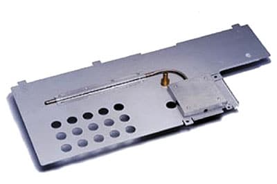 |
Figure 1. Heat pipe and heat spreader combination. (Courtesy of Enertron Corp.)
Active Cooling
This class of solutions encompasses an array of cooling techniques that are diverse and extensive. It is not the intent to review each individual cooling solution, rather to highlight what is available and to provide the salient features of each option. In a broad sense, the cooling options can be categorized as follows:
Heat Sinks and Fan-Sinks without Heat Pipes
Extended surfaces, so-called heat sinks, are by far the most commonly used cooling solutions in the electronics industry. The designs, manufacturing techniques, and materials used in their construction are as diverse as the designers who make them. Conventionally they are used in systems with air movers. At times, because of airflow inadequacy or spatial constraints, a fan maybe mounted on the heat sink, the so-called fan-sink. Or, a heat pipe is also used along with the heat sink to improve thermal transport. The interfacial and spreading resistances in addition to the attachment, as well as designing the heat sink for the right location on a PCB, are the points of contention.
Fluid Flow Management and Enhancement
Although this by itself can not be considered as a stand alone cooling solution, board and system level fluid flow management has shown great promises. The technique involves looking at the flow distribution in the region of interest and attempting to change the layout, whether a board or system, to remove flow stagnation points. As a result, whether a component on a PCB or a PCB in a system, it will have a significantly improved flow-exposure that can often result in the elimination of heat sinks or a lesser capacity cooling solution (Figure 2). This is an area that is often ignored since board or system re-layout are costly if fluid flow optimization is not done a priori.
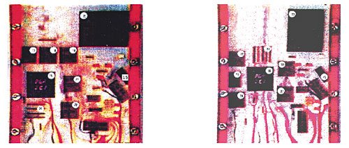 |
Figure 2. Water flow visualization of a flow over a PCB. On the left, the original layout shows multiple stagnation points. On the right, the flow-optimized layout shows minimal stagnation points. (From the author’s short course: “Experimental Methods in Electronics Cooling.”)
Hybrid Cooling
This simply implies a combination of liquid and air cooling for high power dissipation electronics, while minimizing contact resistance throughout the system. In this
Figure 3a, shows a rack/card guide system where the liquid is flowing through the card rack. The heat that is generated within the PCB is conduction through the solid core to the rack where the liquid is used as the transport vehicle to remove it from the system. The illustration on the right in Figure 3a shows a thru-card scheme where
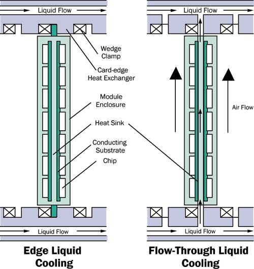 |
Figure 3a. Two hybrid systems for an avionics application: On the left, edge liquid cooling; on the right, thru-card liquid cooling [1].Figure 3b shows the extensive packaging required to make such systems happen. Tightly sealed joints and mechanical contacts with least resistance are required to attain the level of thermal performance required for such a cooling option.
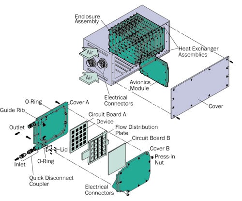 |
Figure 3b. Card and rack level packaging required for hybrid cooling [1].Although I have purposefully avoided the discussion of cooling capacity, the exception to the path may be merited here since these systems are not commonly encountered nor discussed in the open literature. Therefore, Figure 4 shows the removal capabilities of the hybrid systems for different cooling arrangements [1].
The data depicted in Figure 4 clearly show the advantage of, say, subcooled jet impingement and a conventional cooled system, approximately a factor of 13! However, one cannot overlook the packaging requirements to deliver such a cooling solution, as shown in Figure 3b. The cost of these requirements and the attainment of a high reliability cooling system may not make these systems suitable for typical commercially available electronics.
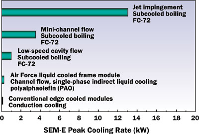 |
Figure 4. Heat removal capacity for different hybrid system as compared with a convection cooled system. [1]
Thermoelectric Cooler (TEC)
TECs are electronic refrigerators that use the electrons to carry energy between the source and sink. The notion of a pump-less refrigerator, albeit highly inefficient, is an attractive concept. However, as shown by a number of researchers in the field, the promise of the TEC being an effective system level cooling solution has not materialized [2]. However, the TEC has been shown to be an enabling technology for spot cooling. One area that has benefited greatly from TEC is optical devices where maintaining a laser temperature at a set level is a must for proper device operation.
(End of Part 1)
In Part 2 of this article, which will appear in the next issue, we will conclude with a discussion of Closed Loop Cooling, Thermosyphons, Direct Immersion with and without Boiling, Refrigeration Cooling Systems, Cryogenics Cooling, and Conclusions.
References for Part 1
- Mudawar, I., “Assessment of High-Heat-Flux Thermal management Schemes”, Proceedings of ITHERM, Las Vegas, NV, USA, 2000.
- Simons, R., “Application of Thermoelectric Coolers for Module Cooling Enhancement”, ElectronicsCooling, Vol. 6. No. 2., pp. 18-24.


