Heat loads of data processing equipment continue to increase at a rapid rate. This increasing heat load has been documented by a Thermal Management Consortium of 17 companies [1] as shown in Figure 1. Also shown in this figure are measured heat fluxes (based on product footprint) of some recent product announcements. The most recent shows a rack dissipating 28,500 watts, resulting in a heat flux based on the footprint of the rack of 20,900 watts/m2. With these heat loads the focus for customers of such equipment is in providing adequate air flow at a temperature that meets the manufacturer’s requirements. Of course, this is a very complex problem considering the dynamics of a data center and one that is only starting to be addressed [2-9]. There are many opportunities for improving the thermal environment of data centers and in improving the efficiency of the cooling techniques applied to those data centers [9]. Only the key factors related to data center thermal management are addressed in this article.
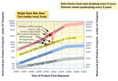 |
Figure 1. Equipment power trends.
Data centers are typically arranged into hot and cold aisles as shown in Figure 2. This arrangement accommodates most rack designs which typically employ front to back cooling and somewhat separates the cold air exiting the perforated tiles (for raised floor designs) and overhead chilled air flow (for non-raised floor designs) from the hot air exhausting at the rear of the racks. The racks are positioned on the cold aisle such that the fronts of the racks face the cold aisle. Similarly the rear of the racks face each other and provide a hot air exhaust region. This layout allows the chilled air to wash the fronts of the data processing (DP) equipment while the hot air from the racks exit into the hot aisle as it returns to the inlet of the air conditioning (A/C) units.
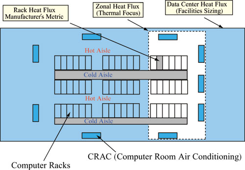 |
Figure 2. Data center thermal management focus areas.
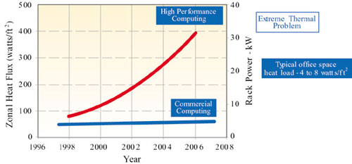
With the arrangement of DP equipment in rows within a data center there may be zones where all the equipment within that zone dissipates very high heat loads. This arrangement of equipment may be required in order to achieve the performance desired by the customer. These high performance zones (shown in Figure 2) can provide significant challenges in maintaining an environment within the manufacturers specifications. Figure 3 shows trends for these high heat flux zones using the equipment power trends of Figure 1. In contrast, a data center that employs a mix of computer equipment with lower power racks is also shown in Figure 3.
Figure 3. Zonal heat fluxes (watts/ft2).
Room Air Flow Designs
Air flow distribution within a data center has a major affect on the thermal environment of the DP equipment located within these rooms. A key requirement of manufacturers is that the inlet temperature and humidity to the electronic equipment be maintained within the specifications. To provide this environment customers of such equipment typically employ two types of air distribution systems. These are briefly described below.
Non-Raised Floor Room Cooling
Cooling air can be supplied from the ceiling in the center of the room, where computers are located, with exhausts located near the walls. Short partitions are installed around the supply opening to minimize short-circuiting of supply air to returns. Similarly cool air from a more distributed area of the ceiling can be supplied with exhaust located around the perimeter or a return in the floor. Alternatively a design employed by the Telecom industry and more recently employed in the computer industry utilizes heat exchangers located above the racks near the ceiling. The racks are arranged using the hot and cold aisle concept where hot air from hot aisles enter the heat exchangers and, once cooled by the heat exchangers, is forced down into the cold aisles using fans mounted to the bottom of heat exchangers.
Raised Floor Room Cooling
Computers typically have many cables connecting the components within a rack and between racks. To maintain a neat layout, a raised floor (also known as false floor or double floor) is used and all interconnect cabling is accomplished under the raised floor. In many cases this space under the raised floor can be used as an air supply plenum with the use of perforated tiles exhausting chilled air. Similarly, it is possible to have a false ceiling (also called a dropped ceiling) in the room with the space above the false ceiling used as the air supply or the return plenum. The air flow can be from floor to ceiling, ceiling to floor, floor to exhausts located in the walls or other locations in the room.
Factors Influencing Rack Inlet Temperatures
The primary thermal management focus for data centers is that the temperature and humidity requirements for the electronic equipment housed within the data center are being met. For example, one large computer manufacturer has a 42U rack configured for front to back air cooling and requires that the inlet air temperature into the front of the rack be maintained between 10 and 32°C for elevations up to 1287 m (4250 feet). Higher elevations require a derating of the maximum dry bulb temperature of 1°C for every 218 m (720 feet) above 1287 m (4250 feet) up to 3028 m (10000 feet). These temperature requirements are to be maintained over the entire front of the 2 m height of the rack where air is drawn into the system. Figure 4 shows a cluster of these racks each dissipating from 7 to 8 kW. Since air enters the front of the each rack over the entire height of the rack, it is a challenge to maintain the temperature within the requirements as stated for all the racks within the data center. Although the inlet air temperatures for all the racks met the requirements, some modifications were still required after the installation. And herein lies the challenge to data center facility operators, especially with the increased equipment heat loads as shown in Figure 1. How do operators maintain these environmental requirements for all the racks situated within the data center and in a data center where the equipment is constantly changing? Without proper attention to the design of the facilities in providing proper airflow and rack inlet air temperatures, hot spots within the data center can occur.
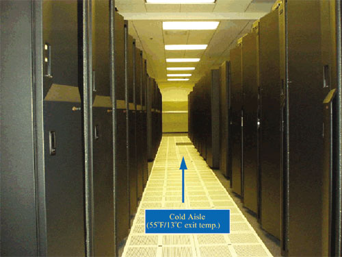 |
Figure 4. Cluster of server racks.
Many factors can affect the environment in the vicinity of the electronic equipment. Some significant factors are listed below along with comments. For brevity only the key findings of the referenced papers are highlighted here. Further information can be obtained from a review of the referenced papers where the specific data center layouts, experimental results, and the associated modeling efforts are described in detail. The purpose here is only to highlight some of the key parameters and their affect on rack inlet air temperatures.
Chilled Air Distribution: Non-Raised Floor(overhead) vs. Raised Floor [2,8]
A simulation of clusters of 4 kW racks with chilled air exhausting the perforated tiles from underneath the raised floor appears in Figure 5. This figure shows the key problem experienced in many data centers today, not to mention the problems that will be realized in data centers of the future with the increased rack heat loads as depicted in Figure 1. Once the lower portion of the rack is satisfied with chilled air drawn into the rack from the raised floor, the upper portions of the rack do not receive any chilled air from the perforated tile in front of the rack and, in order to satisfy conservation of mass needs, to draw air from other portions of the room.
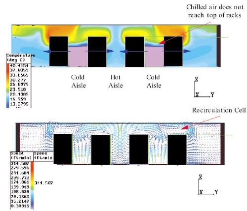 |
Figure 5. Flow/temperature patterns around rows of 4 kW racks.
In Figure 5 the air is primarily drawn from the rear of the rack where the air is much warmer than that from the raised floor. Basically, a recirculation cell is formed at the top of the racks. For example, for a 2 m rack the inlet air temperature at 1 m from the raised floor is typically near the raised floor chilled air temperature. However, at 1.75 m the temperatures can be quite different as shown by the CFD model. Air inlet temperatures can increase by 20°C over the height of the rack due to these recirculation patterns. Similar results are obtained for a non-raised floor where chilled air is supplied from overhead [8]. For this case the rack inlet temperatures are hotter at the lower portions of the rack, just the reverse of what is depicted in Figure 5.
Ceiling Height [2]
When the ceiling height increased from 2.44 m to 3.05 m, the recirculation cell above some racks increased resulting in significant increases in rack inlet air temperatures (up to 9°C for clusters of 4 kW racks and 6°C for clusters of 8 kW racks).
A/C Placement [2]
A/C units placed parallel to rows of racks improved rack inlet air temperatures compared to A/C units placed perpendicular to the rows. The reduction was a result of the recirculation cell above the racks decreasing in strength thereby reducing rack inlet air temperatures. For a cluster of 4 kW racks some locations showed inlet rack temperatures at a height of 1.75 m decreasing by up to 9°C.
Raised Floor Chilled Air Flow Rate [2]
Reducing raised floor tile flow rates by 20% showed large increases in rack inlet air temperatures with many increases in the range of 10-15°C (at rack heights of 1.75 m) for both 4 and 8 kW clusters of racks.
Rack Powers [2]
Comparisons were made with both 4 and 8 kW clusters where the perforated tile flowrate immediately in front of the rack matched the rack flowrate. Racks of higher power (which have higher rack flowrates to maintain the same temperature difference across the rack) had lower rack air inlet temperatures. The higher tile and rack air flowrates aid in moderating the rack inlet air temperatures.
Raised Floor Chilled Air Exiting Hot Aisles [3]
Chilled air exiting the cold aisle is more effective in lowering rack inlet temperatures than bleeding some of the chilled air into the hot aisle. For example, computations were done where the total flow from the perforated tiles match the rack flow, but with 25% of the flow shifted to the hot aisle. In this case the average rack inlet air temperatures (at a rack height of 1.75 m) increased by 7°C, 6°C, and 5°C for 4 kW, 8 kW and 12 kW clusters of racks, respectively, compared to the case where all the flow exited the cold aisle.
Rack Flow Rates [4]
Decreasing rack flow rates for the same perforated tile flow rate resulted in decreased rack inlet temperatures for a cluster of uniformly powered racks. For example, for clusters of uniformly powered 8 kW racks the average inlet temperature of all racks at a height of 1.75m decreased by 12°C when the rack flow rate decreased by half.
Removed Racks [5]
For a high powered rack (12 kW) situated among a lower powered cluster of 4 kW racks, the greatest improvement in rack inlet air temperature for the 12 kW rack occurs when the rack adjacent to the high powered rack is removed. Average inlet air temperatures for the 12 kW rack at a rack height of 1.75 m decreased by approximately 9°C when the adjacent rack was removed.
High Powered Racks amongst Low Powered Racks [6]
Much less perforated tile chilled air flow is required for single high-powered racks situated amongst a cluster of low-powered racks. High-powered racks requiring high rack flows pull chilled air from surrounding perforated tiles thereby requiring much less flow from the tile immediately in front of the high-powered rack. However, some inlet air temperatures of nearby low powered racks increased.
Mal-distribution of Perforated Tile Flows [7]
For clusters of 8 and 12 kW racks, slightly mal-distributed tile flows (less than 8% variation) resulted in significant rack inlet air temperature reductions of up to 8°C for a cluster of 8 kW racks and up to 10°C for a cluster of 12 kW racks. The greatest mal-distribution in perforated tile flows occurred with shorter raised floor heights and more open perforated tiles.
Perforated Tile Openings [7]
Perforated tile openings of 25 and 60% were investigated. For clusters of racks with the same power the 60% open tiles provided more mal-distributed tile flow resulting in reduced rack inlet temperatures. For a cluster of 4 kW racks the average inlet temperature at a height of 1.75 m decreased by about 5°C when perforated tiles increased from 25 to 60% for a raised floor height of 0.15 m.
Under Floor Plenum Height [7]
Plenum heights of 0.15m, 0.30 m and 0.60 m were investigated with the shorter heights showing more mal-distribution of flows exiting the floor tiles and lower rack inlet air temperatures. For clusters of 4 kW racks the average inlet temperature at a rack height of 1.75 m decreased by about 4°C when the raised floor height decreased from 0.60 m to 0.15 m with 60% open tiles. Very little change in average inlet temperature occurred with 25% open floor tiles compared to uniform flow from all the tiles.
Summary
The primary focus for data center operators is that the inlet air temperature to a rack is maintained within the temperature specifications required by the manufacturer of such equipment. The desire to maintain the equipment within the specifications is dependent on a complex set of interdependent parameters some of which were described in this article. Further work is required in this area in order to generate guidelines that can be used by data center operators in optimizing the thermal environment of data centers.
References
- The Uptime Institute, from the white paper entitled “Heat Density Trends in Data Processing, Computer Systems and Telecommunication Equipment” www.uptimeinstitute.org.
- Schmidt, R., “Effect of Data Center Characteristics on Data Processing Equipment Inlet Temperatures”, Advances in Electronic Packaging 2001(Proceedings of IPACK ’01, The Pacific Rim/ASME International Electronic Packaging Technical Conference and Exhibition), Vol. 2, Paper IPACK2001-15870, Kauai, Hawaii, July 8-13, 2001, pp. 1097-1106.
- Schmidt, R. and Cruz, E., “Raised Floor Computer Data Center: Effect on Rack Inlet Temperatures of Chilled Air Exiting both the Hot and Cold Aisles”, Itherm Conference, San Diego, California, June, 2002, pp. 580- 594.
- Schmidt, R. and Cruz, E., “Raised Floor Computer Data Center: Effect on Rack Inlet Temperatures when Rack Flow Rates are Reduced”, Interpack Conference, Maui, Hawaii, July 6 – 13, 2003, to be published.
- Schmidt, R. and Cruz, E., “Raised Floor Computer Data Center: Effect on Rack Inlet Temperatures when Adjacent Racks are Removed”, Interpack Conference, Maui, Hawaii, July 6 – 13, 2003, to be published.
- Schmidt, R. and Cruz, E., “Raised Floor Computer Data Center: Effect on Rack Inlet Temperatures when High Powered Racks are Situated Amongst Lower Powered Racks”, IMECE Conference, New Orleans, La., Nov., 2002.
- Schmidt, R. and Cruz, E., “Clusters of High Powered Racks within a Raised Floor Computer Data Center: Effect of Perforated Tile Flow Distribution on Rack Inlet Air Temperatures”, IMECE Conference, Washington, D.C., Nov., 2003, to be published.
- Patel, C., Bash, C., Belady, C., Stahl, L., and Sullivan, D., “Computational Fluid Dynamics Modeling of High Compute Density Data Centers to Assure System Inlet Air Specifications”, Advances in Electronic Packaging 2001 (Proceedings of IPACK ’01, The Pacific Rim/ASME International Electronic Packaging Technical Conference and Exhibition), Vol. 2, Paper IPACK2001-15662, Kauai, Hawaii, July 8-13, 2001, pp. 821-829.
- Patel C., Sharma. R., Bash, C., and Beitelmal, A., ” Thermal Considerations in Cooling Large Scale Compute Density Data Centers”, Itherm Conference, San Diego, California, June 2002, pp. 767 – 776.

