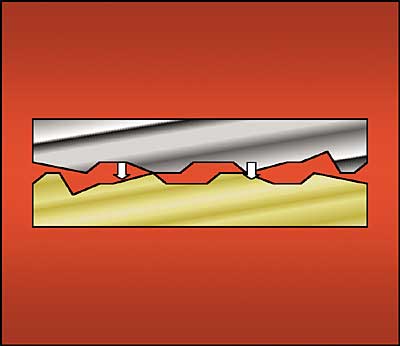
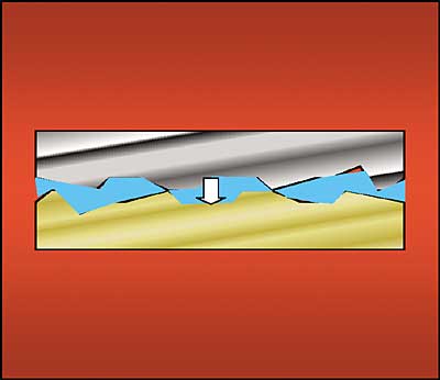
It doesn’t take long for an electronics assembler to realize that a thermal interface material (TIM) is essential when two or more solid surfaces are in the heat path. Standard machined surfaces are rough and wavy, leading to relatively few actual contact points between surfaces. The insulating air gaps created by multiple voids of “contacting” hard surfaces are simply too large a thermal barrier for even modest power applications. The first tactic in overcoming this barrier is to fill the voids and eliminate air by introducing a third material to the heat path that is fluidic and wets the surfaces. For more demanding thermal applications, the second tactic is to use a composite TIM containing fillers that enhance the conduction process of the third material. Yovanovich et al. [1] have calculated that simply replacing air with grease can reduce the thermal resistance by a factor of five or so (depending on the surfaces and contact pressure). As shown in Figure 1, a thermal interface material essentially changes the thermal path between rough-surfaced solids from conduction through point contacts and air to conduction entirely through solids.
 |
Figure 1a. Conduction through point contacts and air between hard surfaces.
Figure 1b. Conduction through TIM filling gaps.
An important property of any TIM is its thermal conductivity, kTIM. Unfilled polymers have a thermal conductivity of about 0.1 W/m�K. All modern TIMs are composites containing particulate fillers that push thermal conductivity up to the 7 W/m�K range. Inorganic particulate fillers include aluminum oxide, magnesium oxide, aluminum nitride, boron nitride, and diamond powder. Metal fillers, notably silver, are also used. Unfortunately, high thermal conductivity alone is not enough to guarantee optimal system performance, as we will show later. In the descriptions of specific material classes, we will characterize performance with thermal resistance (normalized to a unit area on one square cm) that has units K�cm2/W, obtained from a one-dimensional heat flow calculation. In this way, we can account for the interfacial thickness. The specific value in any given application is highly dependent on the contact surfaces and pressures applied. Nevertheless, the ranges provided are representative of each material class. (Note: Many suppliers report resistance values in the mixed unit of K�in2/W. These need to be multiplied by 6.45 to match the units in this paper.)
In addition to thermal performance, TIMs are selected on several other critical criteria as well. Ease of use in assembly and rework are important in high-end applications, as is long-term stability (reliability). The manufacturing process flow often dictates the material selection. In many cases, for example, the TIM is attached to a heat sink in one location while final module assembly occurs in another. Elastomeric pads were developed as an alternative to early grease solutions, largely for the manufacturing advantages they offered. Phase change materials emerged as a technology that captured the thermal performance advantage of grease and combined it with the assembly ease of a solid pad. Often overlooked in the TIM selection process are adhesives and solders. Both offer the unique advantage of secure mechanical bonding, eliminating the need for clamping hardware that the greases, pads, and phase change materials require.
Greases
Greases (also known as thermal compounds) are silicone or hydrocarbon oils that contain various fillers. Historically, they are the oldest class of materials since they readily address the primary goal of eliminating microscopic air pockets. As a group, they are often characterized as “messy” and difficult to apply due to their high viscosity. A more significant concern with application is reproducibly delivering the correct amount to achieve full coverage with the appropriately thin gap. The components require mechanical clamping, and a pressure of about 300 kPa will generally enable optimal thermal performance.
Traditional greases typically yield an interface resistance of about 1 K�cm2/W, while the newest products are in the 0.2 K�cm2/W range. As they are heated during usage, viscosity drops and they tend to further wet the contact surfaces, thus improving performance by lowering the interfacial resistance. An unfortunate consequence in applications that cycle on and off is a phenomenon known as “pump-out” in which the low viscosity grease is forced out of the interface, potentially contaminating neighboring components. In extreme circumstances the interface may go dry.
Due to their long history and widespread application in consumer products, greases are often considered as having peaked in the marketplace. On the contrary, new formulations are being developed to address the specific needs of microprocessor packaging. One microprocessor supplier recommends only two thermal interface materials for interfacing its latest product with a heat sink, and both are recently developed greases [2].
Elastomeric Pads
Elastomeric pads are the logical extension of greases: polymerized silicone rubbers in the form of easy-to-handle solids. With a typical thickness of 0.25 mm, most pads incorporate a woven fiberglass carrier to improve handling and contain inorganic fillers as the greases do. They are supplied as die-cut preforms in the precise shape needed for the application (e.g., all of the standard TO transistor packages). Assembly is therefore very simple with these products. The tradeoff is that high pressures (~700 kPa) are needed to achieve an adequate interface. Furthermore, with a thermal performance range of 1 – 3 K�cm2/W, applications are limited to those with modest thermal requirements.
Thermal Tapes
Thermal tapes were developed as a heat sink attachment method. They eliminate the need for external clamps, hence reducing the overall hardware requirement. Thermal tapes are filled pressure sensitive adhesives (PSAs) coated on a support matrix such as polyimide film, fiberglass mat, or aluminum foil. PSAs adhere to surfaces by contact and with slight pressure applied. They are commonly found on bandages and “sticky” note paper.
As with pads, thermal performance is in the 1 – 4 K�cm2/W resistance range and is highly dependent on surface quality. In fact, the main driver for the use of tapes is often the adhesive property, with thermal performance a secondary consideration. Tapes also have very limited compliance and are generally not suitable for current overmolded BGA packages that have concave top surfaces.
Phase Change Materials
Phase change materials combine the thermal performance of grease with the convenience of an elastomer pad. Originally developed in the 1980s, they came into prominence during the 1990s when they could be easily pre-applied to heat sinks in Taiwan. Final assembly to a microprocessor was then accomplished at a contract manufacturer without the need to handle a “messy” grease.
Phase change materials are predominantly waxes that typically melt in the 50 – 80°C range. Essentially, they are low temperature thermoplastic adhesives. In practice, they are effective conductors of heat both above and below the melt point. When operating above the melt point they are not effective as an adhesive and need mechanical support, therefore they are always used with a clamp applying pressure in the 300 kPa range.
As with pads and tapes, they can be obtained in a variety of configurations, both supported and unsupported, and loaded with fillers to enhance thermal conductivity. Performance levels are very close to grease, in the range 0.3 – 0.7 K�cm2/W. What prevents them from being the perfect solution? Reworkability. Despite not being classified as an adhesive, there is enough adhesion that expensive components are at risk during rework. This is a major consideration for the shift back to grease with the latest high performance microprocessors.
Gels
Gels are another recently developed option that are dispensed like grease, but are then cured to a partially cross-linked structure, thus eliminating the pump-out issue [3]. Thermal resistance levels are comparable to grease, in the range 0.4 – 0.8 K�cm2/W.
Thermally Conductive Adhesives
Thermally conductive adhesives are an option often overlooked by the thermal engineer. Usually epoxy or silicone based formulations containing fillers, they offer a superior mechanical bond that can reduce size and weight of a system. With thermal resistance typically < 1 K�cm2/W, the best performers reach 0.15 K�cm2/W. They do call for robust manufacturing processes though since reworkability is not practical. The payoff with an adhesive is a compact package, a high performance interface and long term reliability.
Solder
Solder is another TIM often overlooked. It represents the ultimate, a solid metal interface with resistance < 0.05 K�cm2/W. Despite the challenges of high temperature processing (and rework), solder is used as a thermal interface where no other viable option exists: first level power die attach. At higher packaging levels the interfaces usually don’t lend themselves to the use of solder and the extended areas make processing very difficult.
Quantification
“Nearly all the present thermal packaging solutions are constrained by the thermal resistances at the solid interfaces along the primary heat removal paths from the chip to the ambient air, notably at the chip surface and at the heat sink base.” [4]
Thermal engineers are constantly seeking “better” thermal interface products. This is usually expressed as a request for higher thermal conductivity. But is that really correct? Is it enough? How critical is the situation? The following analysis attempts to quantify the problem.
It is well known that heat will flow wherever it can and will utilize whatever mode offers the least resistive path, whether conduction, convection or radiation. All electronic systems ultimately remove their heat to the atmosphere by convection. Along the intermediate path there is invariably a conductive section (this is usually the primary path) and somewhere along the way two different materials make contact, hence the need for a TIM.
 |
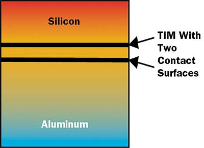
Figure 2. Model diagram for one-dimensional heat flow through five resistive paths: three bulk materials and two interfaces.The simplest, shortest, and arguably most desirable path is direct contact between a silicon device and an aluminum convector (“heat sink”). The TIMs of interest in this instance are thin and readily modeled by one-dimensional heat transfer. In this case (Figure 2) we’ll investigate heat flowing through silicon and aluminum plates interfaced with a TIM that assumes uniform heat transfer along the z-axis with a total resistance of:
(1)It is readily demonstrated [5] that the interface resistance is actually comprised of two new contact resistances plus the bulk resistance of the TIM:
(2)Combining the individual contact values and introducing the single axis bulk conduction relationship yields the resistance dependence on interfacial contact area and thickness:
(3)where t is the material thickness (m), A is its area (m2), and kTIM is the thermal conductivity in W/m�K.
Applying the bulk conduction relationship to the silicon and aluminum as well gives us a total system resistance:
(4)
Table 1. Typical Values of Thermal Conductivity and Resistance
|
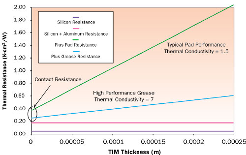
Typical values for silicon and aluminum are illustrated in Table 1. With these base values for aluminum and silicon, the thickness sensitivity for representative TIMs is illustrated in Figure 3. It is readily apparent that, in fact, the interface is a critical link in the thermal path and can account for a significant portion of the thermal management budget. In this model, a 0.2 mm elastomeric pad represents fully 90% of the total system resistance (1.7 K�cm2/W). Significant improvement is obtained with a 0.1 mm grease interface that represents 56% of a 0.4 K�cm2/W total. Clearly, thinner interfaces and higher conductivity improve the situation. But it is also important to recognize that the contact resistance can actually be a more important factor, especially for thermally demanding applications. Increasing thermal conductivity “flattens” the total resistance response, but if accomplished at the expense of contact resistance, no net improvement is accomplished. It is clear that both TIM suppliers and users must address both bulk conductivity and contact resistance to be successful.
 |
Figure 3. Total thermal resistance of solids plus TIM structures.
Conclusion
As long as electronic systems aren’t monolithic (i.e., are built with wide combinations of materials such as metals, polymers, ceramics, semiconductors) there will be a need for thermal interface materials. With electronic systems becoming faster, hotter, more compact, and portable, the need for better TIMs will continue. The winners will address thermal resistance (possibly customized to specific interfaces), will be easy to use in manufacture, will be reworkable when needed, and will have long term reliability.
References
1. Yovanovich, M. M., Culham, J. R., and Teertstra, P., “Calculating Interface Resistance,” ElectronicsCooling, Vol. 3, No. 2, May, 1997, pp. 24 – 29.
2. “AMD Athlon™ 64 Processor Thermal Design Guide,” Publication 26633, Rev. 3.02, February 2003, www.amd.com.
3. Wells, R., Sanders, J., Pecorari, L., and Hunadi, R., “GELEASE™ – A High Performance Alternative to Thermal Grease and Phase Change Materials,” 1998, www.thermoset.com.
4. Bar-Cohen, A., “Computer-Related Thermal Packaging at the Millennial Divide,” ElectronicsCooling, Vol. 6, No. 1, Jan. 2000, pp 32 – 40.
5. Chu, C. P., Solbrekken, G. L., and Chung, Y. D., “Thermal Modeling of Grease-Type Interface Material in PPGA Application,” Proceedings of 13th IEEE SEMI-THERM, 1997, Vol. 1, pp 57 – 63.


