In past issues of Electronics Cooling, methodologies were presented for estimating parallel plate-fin heat sink thermal resistance [1] and pressure drop [2]. The underlying assumption for both articles was that all the flow delivered by the fan is forced to go through the channels formed between the fins. As noted in the second article this is often not the case and much of the flow delivered by the fan may take the path of least resistance by flowing around the heat sink.
 |
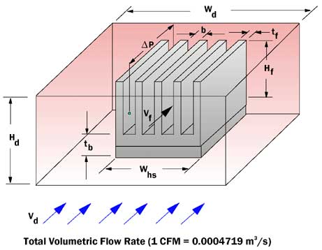
Figure 1. Parallel plate fin heat sink configuration in Hd x Wd flow duct.This article will illustrate the use of simple flow equations (see Table 1) to estimate the air flow that actually passes through the fin passages of the heat sink in the presence of flow bypass. The heat sink geometry (see Figure 1) considered is the same as that in the earlier articles, but the heat sink is assumed to be in a duct of width Wd and height Hd. The flow delivered by the fan is assumed to approach the heat sink and surrounding free flow area with velocity Vd. The total duct flow Gd , is given by
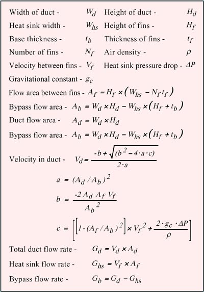
![]() If the average air velocity through the heat sink fin passages is defined as Vf, the flow Ghs through the heat sink is given by
If the average air velocity through the heat sink fin passages is defined as Vf, the flow Ghs through the heat sink is given by
![]() It is assumed that the volumetric flow ratio of the air through the fin passages is constant throughout. The pressure drop,
It is assumed that the volumetric flow ratio of the air through the fin passages is constant throughout. The pressure drop, ![]() P, across the heat sink at the flow rate Ghs through the heat sink is estimated using the method given in reference [2]. The corresponding velocity, Vd, in the duct approaching the heat sink is given by
P, across the heat sink at the flow rate Ghs through the heat sink is estimated using the method given in reference [2]. The corresponding velocity, Vd, in the duct approaching the heat sink is given by
 |
with the coefficients a, b, and c as given in Table 1. The derivation of Equation (3) is given in reference [3]. This velocity may then be used in Equation (2) to calculate the corresponding volumetric flow rate in the duct. If desired the amount of flow bypass may be calculated by subtracting the heat sink flow rate (Equation 2) from the total duct flow rate (Equation 1).
Table 1. Summary of Bypass Flow Equations
 |
To illustrate the application of these equations the same heat sink dimensions used in the preceding articles were used. An aluminum heat sink 50 mm wide x 50 mm long with 0.5 mm thick 25 mm tall fins was assumed. Calculations were performed for configurations of 10, 20 and 30 fins with and without bypass.
For the case with flow bypass, duct dimensions 70 mm wide and 32 mm high were assumed, resulting in 10 mm clearance on either side of the heat sink.
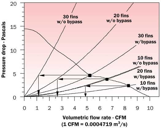
Assuming several air velocities (Vf) through the heat sink, pressure drops (![]() P) and corresponding volumetric flow rates (Ghs) through the heat sink were calculated for the case without bypass as in reference [2]. These results were plotted to obtain the pressure drop curves (w/o bypass) in Figure 2. Equations (1) and (3) were then used to obtain the total duct flow rate (Gd) with bypass (i.e. flow through heat sink + bypass flow) corresponding to each of the assumed air velocities (Vf) through the heat sink. The pressure drops across the heat sink at each of the assumed air velocities through the fins was plotted versus the corresponding total duct flow rate with bypass to obtain the pressure drop curves with flow bypass.
P) and corresponding volumetric flow rates (Ghs) through the heat sink were calculated for the case without bypass as in reference [2]. These results were plotted to obtain the pressure drop curves (w/o bypass) in Figure 2. Equations (1) and (3) were then used to obtain the total duct flow rate (Gd) with bypass (i.e. flow through heat sink + bypass flow) corresponding to each of the assumed air velocities (Vf) through the heat sink. The pressure drops across the heat sink at each of the assumed air velocities through the fins was plotted versus the corresponding total duct flow rate with bypass to obtain the pressure drop curves with flow bypass.
 |
Figure 2. Heat sink pressure drop curves (with and without flow bypass) and fan curve with flow operating points.As in reference [2] the intersections of the fan curve and the pressure drop curves without bypass determine the volumetric flow rates through the heat sink. In a similar manner the intersections of the fan curve with the pressure drop curves with bypass determines the total volumetric flow rate entering the heat duct. As shown in Figure 2, the pressure drop across the heat sink and the duct at positions corresponding to the inlet and outlet of the heat sink is also determined by the intersection of the fan curve and the pressure drop curves with bypass. Projecting horizontally at constant pressure drop to the pressure drop curves for flow through the heat sink (without bypass) gives the amount of flow actually passing through the heat sink.
Having determined the actual flow through the heat sink, the equations outlined in reference [1] were used to calculate the thermal resistance for each heat sink configuration with and without flow bypass. These results are summarized in Table 2.
Table 2. Summary of Volumetric Flow Rates Through Heat Sinks and Corresponding Heat Sink Thermal Resistances (Heat Sink to Air)
|
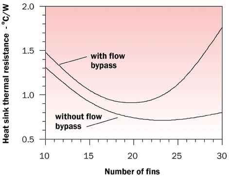
1 1 CFM = 0.0004719 m3/sThe effects of the presence or absence of flow bypass and the number of fins on heat sink thermal resistance, are also shown graphically in Figure 3. As can be seen, the effect of flow bypass on heat sink thermal resistance can significantly increase heat sink thermal resistance as the number of fins increases.
 |
Figure 3. Effect of number of fins on heat sink thermal resistance with and without flow bypass.Although the method presented here can be a useful tool for preliminary tradeoff estimates it should not be construed as a replacement for detailed computational fluid dynamic modeling or experimental verification.
References
- Simons, R.E., “Estimating Parallel Plate-Fin Heat Sink Thermal Resistance,” Electronics Cooling, Vol. 9, No. 1, pp. 8-9, 2003.
- Simons, R.E., “Estimating Parallel Plate-Fin Heat Sink Pressure Drop,” Electronics Cooling, Vol. 9, No. 2, pp. 8-10, 2003.
- Simons, R.E., and Schmidt, R.R., “A Simple Method to Estimate Heat Sink Air Flow Bypass,” Electronics Cooling, Vol. 3, No. 2, pp. 36-37, 1997.


