Control of cooling fans has become increasingly popular as efforts are made to reduce system power consumption and mechanical fan noise. The purpose of including a fan is to reduce temperature and keep it as low as possible. Mean time to failure for a variety of systems increases rapidly as temperature elevates.
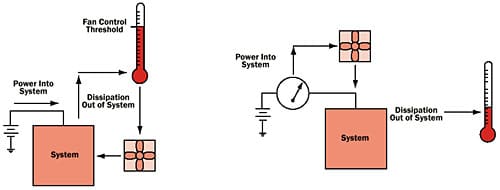
This has brought about a wide choice of thermally based fan control IC’s. Using temperature to control a fan in fact conflicts with the ideal of keeping systems as cool as possible. Thermal fan control requires a temperature rise to enable the fan as depicted in Figure 1a. Proportional controllers make fan speed proportional to temperature, which is even more inappropriate, since it requires even higher temperatures to enable higher fan speeds. Such control strategy is more appropriate in a system where it is desired to stabilize a system at an elevated temperature, rather than to cool it as much as possible.
Fan speed should be based on the thermal load of the system, which is power dissipation. In most electronic systems, power dissipation is directly proportional to power consumption, which is readily measured as the power supply current into the system. In addition to being a true measure of the thermal load, supply current is an instantaneous indicator of thermal load, revealing the need for additional cooling long before the temperature of even on-chip silicon diodes can detect it. Essentially, fan speed should be based on system power supply current as depicted in Figure 1b.
Computers, both desktop and notebook, all require fans and associated control systems. At this time fan control is accomplished thermally. Certainly in computers sensing CPU current can be used to control fans, and this would provide lower operating temperatures than existing methods of fan control. In computers where the manufacturer prefers “stand alone” fan control without software involvement, current sensing is the optimum solution. Computers where software is already involved on a continuous basis with fan control can take advantage of software input to fan control from computer performance monitors and tools that keep track of CPU activity. Fan speed in such a system would be proportional to that CPU activity.
Figure 1a shows a fan control scheme based on temperature that requires a rise in temperature to act. The thermometer has to go up to turn the fan on and make it go faster. This is not a maximum cooling scenario. Figure 1b shows a fan control scheme in which fan speed is controlled by sensing supply current. This makes fan control proportional to the thermal load, eliminating time lags and insuring the lowest possible system temperatures.
|
||||
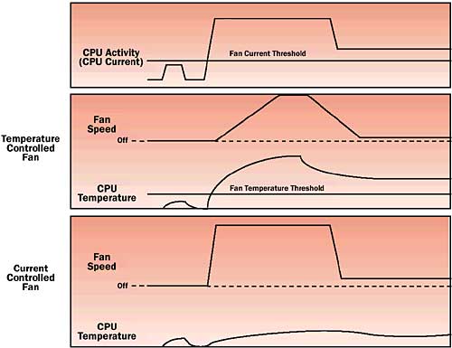
To further illustrate the benefit of fan control by current measurement, compare the graphs of Figure 2. using the example of a computer CPU. The graph shows the power supply current and depicts CPU temperature behavior with a thermally controlled fan and a current controlled fan. The current controlled fan reacts immediately to the thermal load where the thermally controlled fan must wait until temperature rises. The current controlled fan will always run at full speed if full current is being drawn regardless of temperature, insuring the lowest possible operating temperature.
 |
Figure 2. Comparison of CPU temperature behavior for thermally controlled fan vs. current controlled fan. By reacting faster and harder, the current controlled fan prevents large temperature excursions and keeps the CPU as cool as possible.
While this is simple enough on the surface, power supply current varies dynamically and rapidly far more than the natural integration that occurs in temperature measurement. Practical current controlled fan drivers will incorporate integration or delays, in the case of analog circuitry, or algorithms, in the case of processor control, to smooth the fan response.
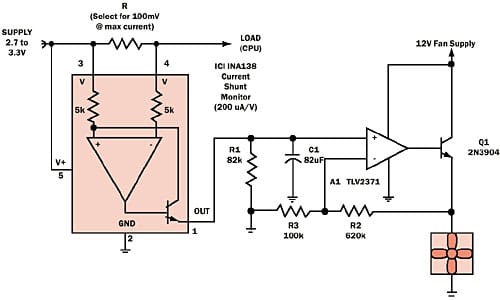
An example of an implementation is shown in Figure 3. Simplify implementing current controlled fan designs by using dedicated high-side current shunt monitoring ICs as shown in the CPU sensing example of Figure 3. IC1 senses CPU current in RS, which is sized for a maximum of a 100mV drop at full rated CPU current. IC1 converts that drop to a current at IC1’s output (200�A/V) with R1 providing a load to develop a voltage output. IC1’s output voltage can only swing to a maximum of 1.7 volts on a 2.7 volts supply determining the value for R1 based on a maximum input of 100mV and IC1’s scale factor. A1 provides the necessary gain (Gain = 12/1.7 = 7) to drive a 12-volt fan from the 1.7 volt output swing of IC1. Q1 buffers A1’s output to provide sufficient current to drive the fan. This very simple realization uses only integration via C1 to smooth the fan response to current fluctuations, with the tradeoff of slowing the fan response. (Arguably the fan response is still much faster than thermal sensing, besides the fact that it forces the fan speed to a setting appropriate to reducing temperature). C1 would normally be found empirically after evaluating the thermal performance of the target system. The value for C1 shown in Figure 3 provides an approximately 10 second time constant.
 |
Figure 3. A simple analog realization of a current controlled fan control. C1 smoothes the fan response and filters short-term current spikes.


