Introduction
Miniaturization, integration of functionality, and the increase of clock speed are recognized business drivers in the electronics industry today. Consequences are the fast increase in power dissipation leading to higher heat fluxes, higher temperatures and larger temperature gradients. Handling these effects makes it more difficult to stay cost competitive, because expensive cooling solutions are needed. Therefore, reducing power dissipation will be a competitive advantage [1].
As Bar-Cohen already stated in 1993 [2], world-class quality of products not only includes performance and reliability of the product, but also demands first-time right designs to shorten the product development period and therefore the time-to-market. Since reliability is influenced by temperature [3] and temperature gradients [4], thermal management should also be taken into account in the early design stages.
The Philips Centre for Industrial Technology (CFT) is a center of competence supporting the Philips Product Divisions and a number of high-technology companies outside Philips, particularly in the fields of mechatronics, electronics, process technology, materials analysis, assembly, and industrial support. The support concerns all levels of the product design, which means that, for the Philips CFT-competence, cooling of electronics thermal analysis is performed at the component, module, or system level.
This article deals with thermal roadmaps as we started using them in 2001 in the framework of the cooling of electronics competence. These thermal roadmaps include graphs of power density or heat flux versus year of introduction, product versus applied cooling mechanism, etc. In this way a large set of thermal roadmaps can be collected on the three levels (component, module, system). In the electronics cooling community a well-known example of a thermal roadmap is the trend in power dissipation of microprocessors [5,6] and CPUs.
Using the combination of thermal roadmaps and experience with thermal issues in products already on the market, three goals can be defined:
- Identify the thermal trends in electronics: problems (e.g., increase in power dissipation) versus solutions (e.g., applied cooling mechanisms).
- Identify future thermal needs and derive technology programs.
- Use the thermal roadmaps as a quick reference for new products.
When combined, the three goals allow matching the development of our cooling of electronics competence to the thermal needs of future electronic products.
The objective of this article is to present some examples of thermal roadmaps, discuss their underlying ideas, and show how the roadmaps can be exploited.
Thermal Roadmaps in the Product Design
In many cases, thermal experts face fire fighting. They are involved at a late stage when tests show that the temperatures are above specifications. A new design loop leads to an increase in the time-to-market
Increasing the awareness of electrical and mechanical designers of the importance of thermal aspects can lead to fire protection, (Figure 1). Thermal design is started early, simultaneously with electrical and mechanical design. This goes together with optimal solutions, design freedom, and short time-to-market (“first time right” design). See also [7].
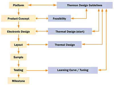 |
Figure 1. Thermal design: fire protection.A few examples of thermal roadmaps appear in the next sections.
Ideal Case of Thermal Roadmaps
To explain the principle of thermal roadmaps we discuss an ideal case: a component attached to a heat sink plate using a thermal adhesive (Figure 2).
 |
Figure 2. Component attached on heat sink plate using a thermal adhesive.The allowed heat flux before a new cooling method has to be used is calculated. We assume that the maximum allowed component case temperature is 100°C and that all dissipated heat is transferred to the heat sink. The case temperature of the component as a function of heat flux is shown in Figure 3 for three situations.
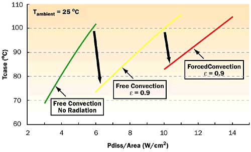 |
Figure 3. Case temperature of a component attached to a heat sink as function of dissipated power per component area for different cooling solutions.For a heat sink with free convection and emissivity = 0, the maximum case temperature is reached for a heat flux of 6 W/cm2. Increasing
to 0.9 a heat flux of 10 W/cm2 can be achieved (67% higher).When using a fan, a heat flux of 13 W/cm2 can be achieved. Not all possible cooling solutions are shown in Figure 3. For example, changing the heat sink material or applying heat pipes can be included and lead to different curves. In references a more extensive discussion is given on possible cooling solutions for several applications.
Figure 3 is an ideal example of a thermal roadmap, since a clear trend can be identified, and it is clear when new cooling solutions need to be applied.
Examples of thermal trends in products from Philips Lighting Electronics and Philips Semiconductors are given in the next two sections. Another example of a flat TV monitor may be found in [8].
Trends in Ultra High Pressure (UHP) Lamp Drivers
UHP lamp drivers from Philips Lighting Electronics (PLE) are used in projectors. As the tendency of these projectors is to become smaller the electronic gear should be smaller as well (Figure 4).
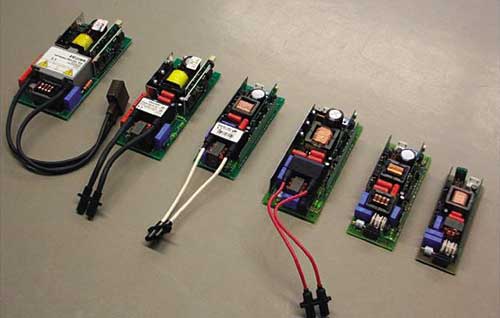 |
Figure 4. Size reduction in UHP lamp drivers.As a consequence the power density of the lamp driver increases and thermal problems arise. Measures have been taken in the evolving products to solve thermal issues in the lamp driver. The temperature levels are reduced by using different package and connection methods. Diodes and FETs used to be screwed onto heat sinks. However, in the latest designs, multi-layer boards and IMS (Insulated Metal Sheet; epoxy material replaced by aluminum) are used instead of the heat sinks.
Boards with improved thermal conductance are introduced to increase the effective surface of the PCB that is used for heat transfer to the passing air. In Figure 5, the cooling capacity of the fan is shown for two different velocities as a function of the relative volume. In this figure the power density trend is also plotted.
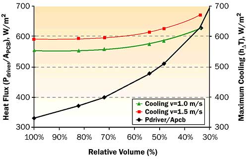 |
Figure 5. Heat flux (Pdriver/APCB) and maximum cooling capacity (hTmax) in W/m2 as function of relative volume for UHP lamp drivers.From experience, we know that the average PCB temperature has to be below a specified maximum temperature Tmax:
The power dissipation in the driver is almost completely transported to the PCB. Therefore the average PCB temperature is given by:
where:
h = Heat transfer coefficient from PCB to air in W/m2k
A = PCB area in m2
Tpcb = Average temperature of the PCB in °C
Tair = Inlet temperature of the air in °C
The maximum power dissipation (Pmax) in the driver is given by:
If Pdriver is above Pmax, the heat transfer from PCB to air has to be increased.
From Figure 5 it is seen that the provided airflow (1.0 m/s) is not enough for the last design. Therefore the airflow through the driver was increased. For a further size reduction of the driver the cooling will again not be sufficient. Consequently the airflow should be increased and/or other cooling strategies should be applied.
From the different product generations shown in Figure 4 it is seen that the drivers have changed drastically. Several components are replaced and functions of components are integrated in other components.
Several size reductions have been made in the consecutive designs based partially on cooling considerations. In order to further decrease the size of new generations UHP drivers one should develop smaller coils making coil cooling crucial. Options to improve the cooling of the coils by increasing the heat flow to the PCB and by increasing the heat exchange area in contact with the airflow are under investigation.
Trends in RF Power Modules
Philips Business Line RF Modules is a player in the mobile communication market. They develop power amplifier (PA) modules for GSM products and provide other cellular phone markets with similar modules, such as the Bluetooth module for wireless communication. An example of a PA module for mobile phones appears in Figure 6 [9]. A PA module is a typical example of miniaturization and increasing functionality. A complete function can be performed with just one module.
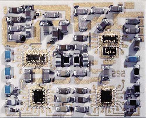 |
Figure 6. Typical power amplifier module – size: 11×14 mm.Figure 7 shows the trend in dissipated power per die area in a PA module. A strong increase is seen. It is expected that in the near future this heat flux will increase exponentially.
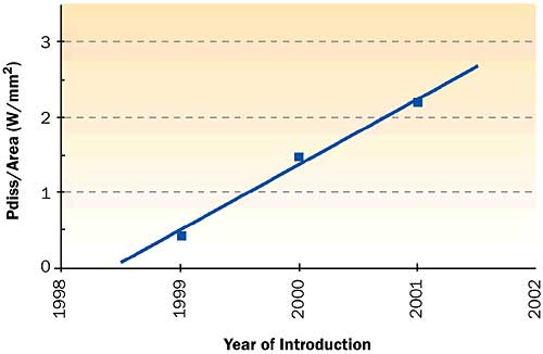 |
Figure 7. Trend in dissipated power per effective die area of the die with the highest dissipation in the PA module.Figure 8 shows the thermal resistance Rth of four possible multi-layer substrates as a function of substrate area. Adding vias reduces the thermal resistance Rth for substrate 1 by approximately 90%. Further reduction in Rth (substrates 2 and 3) is achieved by a combination of different vias (dimensions, pitch, and properties) and different substrate material. Substrates with higher thermal conductivity have a better heat spreading, combined with a better heat transport from top to bottom.
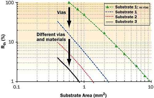 |
Figure 8. Trend in substrate thermal resistance (in %): effect of including vias and using different substrates.The thermal resistance of the substrate cannot be reduced without limit. Sooner or later “traditional” solutions will not cope anymore with the increasing power density demands. Therefore, to solve future thermal problems, attention is shifting from optimizing the amount of copper in the multi-layer substrate and using more and larger vias towards using different materials.
How to Use the Thermal Roadmaps?
Gathering information from completed projects helps to provide more insight in possible trends. Roadmaps combined with cooling capacity (Figure 5) are helpful in understanding the urgency to find new cooling techniques and when these techniques should be available.
The third goal of thermal roadmaps is using them for quick reference:
- Position the new product on thermal roadmaps of comparable, already existing products (during feasibility study).
- Use the experience of the thermal solutions for those products to make an assessment on the thermal behaviour and possible solutions for the new product.
The thermal roadmaps should not be used as final thermal analysis, but if these roadmaps can convince the product developer to pay serious attention to thermal management in the early stages of the overall design process, half the battle is won and a first-time right design can become reality.
Summary and Conclusions
The use of thermal roadmaps in cooling of electronics is described. The thermal roadmaps serve three goals:
- Identifying thermal trends.
- Identifying future thermal needs and developing technology programs.
- Using the roadmaps as quick references and increasing the product developer’s awareness of the importance of thermal design.
Acknowledgments
The authors wish to thank Nelis Mies from Philips Lighting Electronics and Jan Mooij of Philips Semiconductors Business Line RF Modules for their cooperation. Also Erik Eggink, Roger van Galen and Peter Maessen (all Philips CFT) are thanked for their contributions.
References
- Power Dissipation in High-End Microprocessors, Prismark Partners LCC, Cold Spring Harbor NY, USA, Feb. 2002.
- Advances in Thermal Modeling of Electronic Components and Systems, Volume 3, Editors: Bar-Cohen, A. and Kraus, A.D., ASME press, NY 1993.
- Lasance, C.J.M., “Thermal Management of Air-Cooled Electronic Systems: New Challenges for Research”, Proceedings Eurotherm, seminar 29, Delft 1993.
- Lasance, C.J.M., “The European Project PROFIT: Prediction of Temperature Gradients Influencing the Quality of Electronic Products”, Proceedings SEMITHERM XVII, 2001, pp 120-125.
- Azar, K., “The History of Power Dissipation”, ElectronicsCooling, Volume 6, No. 1, 2000, pp 42-50.
- Azar, K., “Managing power requirements in the electronics industry”, ElectronicsCooling, Volume 6, No. 4, 2000, pp. 12 – 25.
- Lasance, C.J.M., “The Need for a Change in Thermal Design Philosophy”, ElectronicsCooling, Volume 1, No. 2, 1995, pp. 24-26.
- Luiten, W., “Cooling a Flat TV monitor”, ElectronicsCooling, Volume 9, No. 2, 2003, pp. 22-28.
- The Prismark Wireless Technology Report, Prismark Partners LCC, Cold Spring Harbor NY, USA, July 2002.


