Introduction
In the majority of air-cooling applications, openings or vents are provided in the enclosure or box in which the electronic components are housed. The required cooling air is drawn in from outside the box by fans or blowers. In some applications, however, there may be airborne particulates or other substances in the air that would be injurious to the electrical components in the box, and it is necessary to totally seal the box. In such cases a closed-box cooling approach similar to that shown in Figure 1 may be used. The heat picked up by the air circulating over the components is rejected to outside air via the air-to-air heat exchanger mounted in one of the walls of the box. Unfortunately, a temperature penalty equal to the difference between the temperature of the air exiting the hot side of the heat exchanger (Th-out) and the temperature of the outside air (Tc-in) entering the cold side of the heat exchanger is incurred. Consequently, the temperature of components within the box will be higher than if they were directly cooled with outside air.
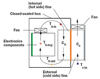 |
Figure 1. Closed box air-cooling configuration with double-sided heat sink air-to-air heat exchanger.The increase in the temperature of the air entering the electronics section (with reference to the outside air temperature) may be calculated using the following equation:
 |
where qL is the total heat dissipation within the box, is the effectiveness of the heat exchanger, and Cmin is the smaller of the inside (i.e. hot side) air heat capacity rate (Ch) or the outside (i.e. cold side) air heat capacity rate (Cc). Equation 1 is similar in form to that given in an earlier article addressing a water-to-air hybrid cooling system [1]. In the system under consideration here, the water loop has been replaced with an internal airflow loop and a double-sided heat sink is used instead of a water-to-air finned tube heat exchanger.The air heat capacity rates in Equation 1 are readily calculated and are equal to the products of the mass flow rate (
x cp) and specific heat for each air stream or:
 |
where is the density of air and Vh and Vc are the volumetric airflow rates on the hot and cold sides of the heat exchanger respectively.In some cases the average air temperature, Th-avg, through the electronics section is used as the reference temperature. Then the average cooling air temperature through the electronics section is given by:
 |
Heat Exchanger Effectiveness
For Equations 1 and 4 to be useful, the effectiveness, , must be known. Heat exchanger effectiveness is the ratio of the actual heat transfer rate of a heat exchanger to the thermodynamically limited maximum possible heat transfer rate in a heat exchanger of infinite area. It is a function of heat exchanger geometry, structure, and the hot and cold side airflow rates. Values of effectiveness for heat exchangers may sometimes be found in vendor literature. For the purposes of this Calculation Corner, a double-sided counter-flow heat sink heat exchanger, shown in Figure 2, will be considered and a procedure to estimate effectiveness will be outlined.
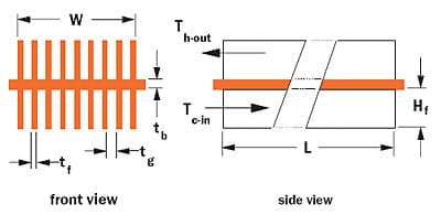 |
Figure 2. Double-sided heat sink used as counter-flow heat exchanger.For a counter-flow heat exchanger, effectiveness is given by:
 |
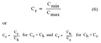
where Cr is the ratio of airflow heat capacity rates given by:
 |
Comparable formulas for effectiveness of other heat exchanger configurations and types may be found in references [2] and [3].
Determining NTU
The term, NTU, in equation (5) is a widely used dimensionless parameter called the number of heat transfer units. It is a measure of the heat transfer size of the exchanger, the greater the number of NTUs the closer the heat exchanger approaches the thermo-dynamic limit. The number of NTUs is given by:
 |
where U is the overall unit thermal conductance of the heat exchanger and A is the area. For the double-sided heat sink heat exchanger U � A is given by:
 |
where Rh and Rc are the convective thermal resistances on the hot side (inside the box) and cold side (outside the box) respectively of the double-sided heat sink and Rb is the thermal conduction resistance across the base of the heat sink.
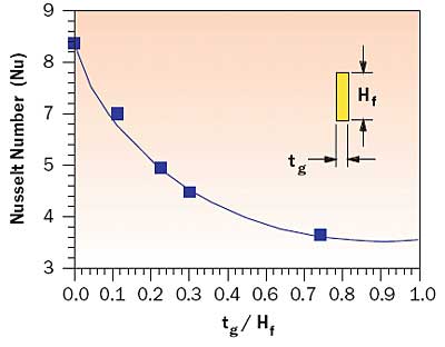 |
Figure 3. Laminar Nusselt number versus flow passage aspect ratio (adapted from [4]).The convective thermal resistance on each side of the heat sink heat exchanger is a function of the convective heat transfer coefficient, fin surface area, and fin thermal efficiency. For the purposes of this analysis, fully developed laminar flow and heat transfer is assumed. Under this condition, the Nusselt number is a function of the flow passage geometry between the fins. As shown in Figure 3, an equation relating Nusselt number to aspect ratio was fitted to values of Nusselt number presented in reference [4]. This equation is:
The heat transfer coefficient, h, acting on the fins is then calculated from:
 |
where kair is the thermal conductivity of air and Dh is the hydraulic diameter of the flow passages between the fins given by:
 |
The convective thermal resistance, R, on each side of the heat sink is given by:
 |
where Af is the lateral surface area of all the fins on the heat sink side being considered, Ab is the exposed base area on that side, and f is the thermal efficiency of the fins. The thermal efficiency of the fins is given by:
 |
where m is given by:
 |
and kf is the fin thermal conductivity.
The conduction thermal resistance across the base is given by:
 |
The foregoing equations may be readily automated using mathematical software, such as Mathcad® or MATLAB®, or any of the common spreadsheet programs. If the reader chooses to automate these calculations, one word of caution is order. When the air heat capacity rates of the hot and cold flow streams are equal, Cr is equal to 1. Examination of Equation 6 shows that this will cause the exponents of the exponential terms in the numerator and denominator to go to zero with an overall result of zero divided by zero. To avoid this difficulty set Cr to 0.999 or 1.001 for Cr equal to 1.
Example Calculations
To illustrate the application of these equations calculations were performed for an aluminum double-sided heat sink with the following dimensions:
| Width (W) | = | 150 mm |
| Length (L) | = | 150 mm |
| Base thickness (tb) | = | 5 mm |
| Fin height (Hf) | = | 25 mm |
| Fin thickness (tf) | = | 1.5 mm |
| Fin gap (tg) | = | 2.3 mm |
| Number of fins | = | 40 |
Applying equations 8 – 15, it was found that these dimensions result in a convective thermal resistance of 0.083 °C/W on each side of the heat exchanger and an overall unit thermal conductance of 6.0 °C/W. Further calculations revealed that increasing the fin height on both sides of the heat exchanger to 70 mm would approximately double the unit thermal conductance.
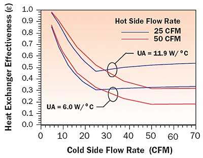 |
Figure 4. Effect of flow rates and UA on double-sided heat sink counter-flow heat exchanger effectiveness.Equations 1 – 7 were then applied to determine the effectiveness and the increase in the temperature of air entering the electronics section above the temperature of the outside air entering the cold side of the heat exchanger. Air flow rates of 25 (0.0118 m3/s) and 50 (0.0236 m3/s) CFM were used on the hot side of the heat sink and flow rates ranging from 5 (0.0024 m3/s) to 70 (0.0330 m3/s) were used for the cold side. The effect of flow rate and overall thermal conductance on the calculated heat exchanger effectiveness is illustrated in Figure 4. The corresponding increase in the temperature of air entering the electronics section above the temperature of the outside air is shown in Figure 5 for the same conditions.
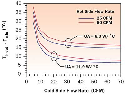 |
Figure 5. Temperature increase of cooling air entering electronics section above external air temperature.It may be noted from inspection of Figure 5 that the air entering the electronics section is actually cooler with a lower flow rate through the hot side of the heat exchanger. Although these results may seem counter-intuitive, they may be understood by examining Figure 6. Figure 6 shows the temperature increase above ambient (i.e., temperature of air outside the enclosure) for: 1) the air entering the electronics section (Th-out – Tc-in); 2) the average air temperature in the electronics section (Th-avg – Tc-in); and 3) the air leaving the electronics section and entering the hot side of the heat exchanger (Th-in – Tc-in). For low airflow rates within the enclosure the temperature rise of the air passing over the heat dissipating electronics will be the greatest, resulting in the highest inlet air temperatures to the hot side of the heat exchanger. Conversely, the combination of a high temperature difference (Th-in – Tc-in) and low air heat capacity rate at the low flow will result in the greatest reduction in the temperature of the warm air passing through the hot side of the heat exchanger. As the hot side airflow rate is increased these two effects are reduced, resulting in an increase in the temperature of the air entering the electronics section and a reduction in the temperature of the air entering the hot side of the heat exchanger. As one might expect, the average cooling air temperature within the electronics section decreases with increasing airflow in the box.
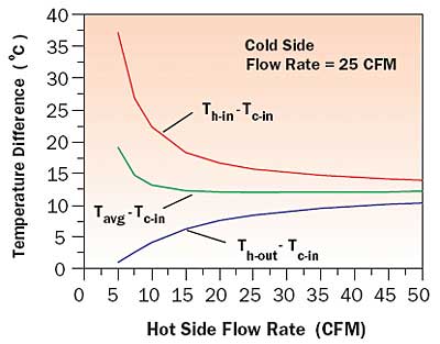 |
Figure 6. Effect of hot side airflow rate on air temperatures within closed box.
References
- Simons, R.E., “Estimating Temperatures in a Water-to-Air Hybrid Cooling System,” ElectronicsCooling, Vol. 8, No. 2, May 2002.
- Incropera, F.P., and DeWitt, D.P., Fundamentals of Heat and Mass Transfer, John Wiley and Sons, New York, NY, 1985
- Kays, W.M., and London, A.L., Compact Heat Exchanger, 3rd ed., McGraw-Hill, New York, NY, 1984.
- Kays, W.M., and Crawford, M.E., Convective Heat and Mass Transfer, McGraw-Hill, New York, NY, 1990.


