Introduction
The electronic industry requires increased forced-air cooling limits to cool high-end server CPUs adequately. Improving air-cooled heat sink thermal performance is one of the critical areas for increasing the overall air-cooling limit. One of the challenging aspects for improving heat sink performance is the effective utilization of relatively large air-cooled fin surface areas when heat is being transferred from a relatively small heat source (CPU) with high heat flux. To meet the next generation CPU thermal requirements with a low profile heat sink, we will describe three heat sink technologies (i.e., embedded heat pipe; vapor chamber; and oscillating/pulsating heat pipe) and their associated prototypes. Each of these technologies uses internal liquid-to-vapor phase change to spread the local CPU heat efficiently to the air-cooled fin structure.
The increased electrical performance required by the computer industry has created thermal design challenges due to both increased power dissipation from the CPU and spatial envelope limitations. Local hot spot heat fluxes within the CPU are exceeding 100 W/cm2, while the maximum junction temperature requirement is 105°C or less. The heat sink requirements for this study are,
- Sink-to-Air Thermal Resistance: 0.18°C/W
- Heat Source Size: 16 x 16 mm
- Power: 150W (uniform heat flux)
- Pressure Loss: 42 Pa
- Flow Rate: 35 cfm (0.0165 m3/s)
- Flow Direction: Front-to-back (perpendicular to gravity)
- Spatial Envelope (H x W x Flow Length): 50 x 115 x 150 mm
- Mass: 680 grams
- Altitude: Sea level
- Orientation: Side heating
An all-metal heat sink was optimized by means of a commercial CFD software tool to yield the minimum sink-to-air thermal resistance, while not exceeding the pressure loss and mass requirements. This heat sink has a 4 mm thick copper base and 70 aluminum fins. Each fin is 0.28 mm thick. This article shows that for the above requirements, the thermal resistance of the all-metal heat sink design is 44% greater than the measured thermal resistance of the prototype heat sinks tested. Additionally, the thermal performance achieved by these prototype heat sinks exceeded the thermal performance levels for all the submitted competitive designs and prototypes, which utilized similar fluid phase change technologies.
Experimental Verification Testing and Setup
The above requirements for each prototype were verified through experimental testing initially conducted at the companies providing the prototypes. Final verification testing was conducted at the Sun Microsystems R&D facility in San Diego, CA. Test results attained by the prototype suppliers agreed relatively well with the final verification test results. The maximum difference in measured thermal resistance attained by all of the test facilities was less than 10% for any given flow rate.
Heat sink thermal performance and pressure drop experiments were conducted at Sun Microsystems in a wind-tunnel system (Figure 1). The test set-up consisted of a fully ducted airflow channel, a heater block under the heat sink, an airflow test chamber to measure airflow rate, and an air-mover. The duct cross sectional area was the same as that of the heat sink to create a fully ducted airflow. Two pressure taps and two thermocouples located upstream and downstream of the heat sink were used to measure the static pressure and airflow inlet and outlet temperatures respectively. The airflow test chamber, located downstream of the airflow channel, used calibrated nozzles to measure the airflow rate accurately. The blower was operated in the suction mode to move air from the flow channel to the airflow test chamber. The airflow rate was calculated from measured pressure difference across the nozzle.
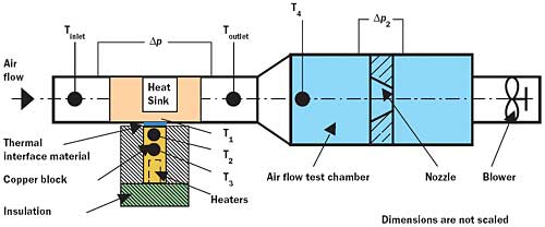 |
Figure 1. Verification test setup and wind tunnel.A fiberglass-insulated copper block with embedded AC cartridge heaters provided power input for the heat sink. Two thermocouples T2 and T3, located below the heater block/heat sink interface surface, were used to measure the actual power input to the heat sink by assuming one-dimensional conduction along the heater block. A commercially available, high-performance thermal grease (with an effective thermal conductivity of 3.5 W/mK) served as the thermal interface material between the heat sink and the heater surface. The heat sink base temperature was measured by embedding thermocouple T1 0.5 mm above the bottom surface of the heat sink base. All thermocouples were calibrated in a temperature controlled water bath with resolution of 0.01°C. In the verification test work the power level was fixed at 150 W and data was recorded after temperatures in the heat sink base and heater block were allowed to reach steady-state for a given air flow rate.
Embedded Heat Pipe Heat Sink
The embedded heat pipe [1,2] heat sink prototype appears in Figure 2. The prototype supplier optimized the design by using both internally developed design tools and a commercial CFD software tool. The supplier indicated that the performance advantage results from design methods that balance the internal and external heat pipe geometry to minimize the intrinsic temperature drop in the heat pipes. This approach distributes the heat over the base of the heat sink. The joining processes minimize the interfacial temperature drops to get the heat into and out of the heat pipes. Other embedded designs have a lower performance because they do not achieve this balance successfully.
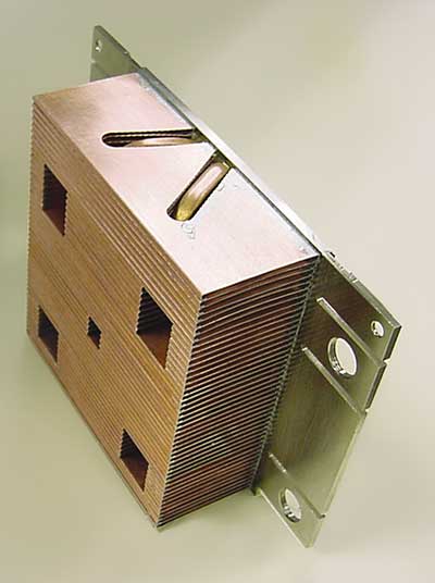 |
Figure 2. Embedded heat pipe heat sink prototype.A heat pipe may be defined as a two-phase (liquid-vapor) device that provides a very high unidirectional thermal conductance for the efficient transport of heat along its length. It consists of a vacuum-tight container lined with a wicking structure on its inner surfaces and filled with a working fluid, which exists in both liquid and vapor states within the container. The working fluid absorbs heat and evaporates wherever the container is hot, carries the heat by physically flowing as a gas through the vapor core to the cooler parts of the container, liberates heat and condenses into a liquid there, and returns through the wick to the hot regions, thus completing a thermodynamic cycle. The temperature differences between the hot and the cold regions within the vapor core of the heat pipe depend only on the pressure drop that the vapor experiences as it flows through the vapor core. This temperature drop is typically quite small, giving the heat pipe an effective thermal conductance significantly greater than that of copper. The wicking structure enhances evaporative heat transfer at the evaporator and provides the motive force to return the liquid phase back from the condenser to the evaporator by capillary action when gravity cannot be utilized to return the liquid.
Vapor Chamber Heat Sink
The prototype vapor chamber [3] heat sink, appearing in Figure 3, is a 3-dimensional heat pipe located in the heat sink base. It represents a relatively new technology that became commercially available during the mid-1990s, versus the traditional unidirectional heat pipe technology available for over 25 years. The prototype supplier carried out an aggressive development effort, which allowed the wick thermal resistance to decrease by 50%, thereby offering an advantage over other heat sinks incorporating vapor chamber technology.
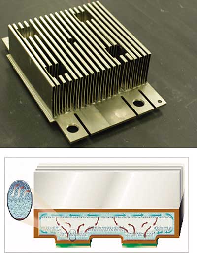 |
Figure 3. Vapor chamber heat sink prototype and illustrated liquid-vapor heat/mass transfer.The vapor chamber minimizes the spreading resistances in the heat sink base by allowing the heated vapor to make full contact between the heat input region and the base of the heat sink fin structure. Figure 3 also illustrates the liquid-to-vapor heat/mass transfer operation when two heat sources are present. The omnidirectional vapor flow allows the heat to flow in all directions, thus minimizing the temperature gradient over the heat sink base area.
Oscillating/Pulsating Heat Pipe Heat Sink
The oscillating heat pipe [4] heat sink prototype appears in Figure 4. In this case, the fin structure flow length is 47.5 mm. Figure 4 also illustrates heat transfer and fluid flow direction. Unlike the previously described prototypes, the oscillating heat pipe heat sink does not contain a wicking structure.
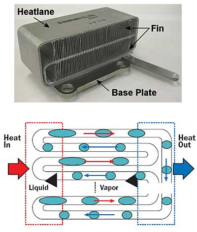 |
Figure 4. Oscillating heat pipe heat sink prototype and illustrated liquid-vapor heat/mass transfer. Note: The discontinuity of lines at the lower right and the vertical row of black dots at the center (to the left of “Vapor”) indicate that the flow path/serpentine duct is repeated several times. Blue circles are vapor bubbles. Blue oblongs are vapor slugs. The remaining white background region inside the serpentine-shaped ducting is liquid. Black arrowheads indicate which regions of the flow through the ducting are liquid and which are vapor.Similar to vapor chamber technology, the oscillating/pulsating heat pipe is a relatively new technology, invented in 1994 by Mr. Akachi [5]. A flat extruded, aluminum plate incorporates both the working fluid and an undulating turned capillary tube. For successful operation, liquid slugs and vapor bubbles must coexist inside the capillary tube along its length (Figure 4). The extruded aluminum plate is formed into a scroll-like shape (Figure 4) to spread heat not only horizontally, but also vertically, thereby providing 3-dimensional heat spreading.
Dr. Polasek [6] described the physics for the oscillating fluid flow and heat transfer as follows: “When one end of the undulating capillary tube is subjected to high temperature, the working fluid inside evaporates and increases the vapor pressure, which causes the bubbles in the evaporator zone to grow. This pushes the liquid column toward the low temperature end (condenser). The condensation at the low temperature end will further increase the pressure difference between the two ends. Because of the interconnection of the tube, the motion of liquid slugs and vapor bubbles at one section of the tube toward the condenser also leads to the motion of slugs and bubbles in the next section toward the high temperature end (evaporator). This works as the restoring force”. As a result the force of gravity has a minimal effect on fluid flow direction.
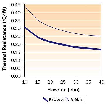 |
Figure 5. Sink-to-air thermal resistances for the prototypes and the optimized all-metallic heat sink.
Results
The measured sink-to-air thermal resistance for the tested prototypes appear in Figure 5. At the design flow rate of 35 cfm (0.0165m3/s), the maximum resistance of these prototypes met the requirement of 0.18°C/W. Figure 5 also shows that, for any given flow rate, the range in thermal resistance for these prototypes was typically °C/W. In addition, the results show that at the 35 cfm (0.0165m3/s) airflow rate, the optimized all-metal heat sink yielded a thermal resistance of 0.26°C/W.
Summary
The measured test results verified that all of the prototypes, which utilized liquid-to-vapor phase change technologies, met the heat sink design requirements, including the critical 0.18°C/W sink-to-air thermal resistance. The optimized all-metallic heat sink design yielded a 0.26°C/W sink-to-air thermal resistance. This study shows that the use of the appropriate technology needed to meet the requirements should be determined on an application-by-application basis, and be based on the technological strengths developed within individual companies. This can only be done when thermal solution providers and customers work together to
Acknowledgments
The authors acknowledge the contributions towards this article made by the prototype development engineers and their respective companies that provided the
References
- Wu, R., ” Heat-pipe type radiator and method for producing the same”, United States Patent 6435266, August 20, 2002.
- Cheung, C., Moore,M., Prosperi, R., “Channel Connection for Pipe to Block Joint”, United States Patent Application No. 20010050165, December 13, 2001.
- Grubb, K., “CFD Modeling of a Thermal-Base Heat Sink”, http://www.thermacore.com/papers.htm.
- Katoh, T., Xu, G., Vogel, M., Novotny, S., ” New Attempt of Forced-Air Cooling for High Heat-Flux Applications, 9th ITherm conference (Intersociety conference on Thermal and Thermomechanical Phenomena in Electronic Systems), Las Vegas, NV, June 2004.
- Akachi, H., “Structure of a Heat Pipe”, United States Patent No. 4921041, May 1, 1990.
- Polasek, F., Rossi, L., “Thermal; Control of Electronic Equipment by Heat Pipes and Two-Phase Thermosyphons”, 11th IHPC (International Heat Pipe Conference), September 1999.


