Introduction
Water cooling of computers was introduced more than twenty years ago, but had disappeared from the mainstream by the mid 1990s. The conversion of chip technology from bipolar to CMOS (complementary metal oxide semiconductor) was the main reason. As chip powers continue to increase, water cooling appears likely to become mainstream again. In the current market, the major benefits of changing from air to water cooling is increased packaging density and lower power noise. Among the systems most likely to benefit are rackmount servers, both 1 unit (1U = 44.45 mm) and blade configurations with even more severe space requirements.
In the near future, water cooling of processors and air cooling of other components may be introduced. The water (or refrigerant) used to cool the processors would transfer heat to the outside environment, probably through the building water supply, avoiding the CRAC (computer room air conditioner) units. The capital cost, energy consumption and floor space required by the CRAC units would be significantly reduced. In a case study by Prechtl and Kurtz [1], a total (server plus cooling) power reduction of 23% and CRAC power reduction of 50% were found.
Nomenclature
| A | wetted surface area | m2 |
| C | thermal conductance | W/K |
| Cp | thermal capacity | J/kgK |
| ε | effectiveness | – |
| h | heat transfer coefficient | W/m2K |
| mass flow rate | kg/s | |
| NTU | number of transfer units | – |
One significant difference with air cooling is the volumetric thermal capacity of water, close to 4000 times that of air. The volume of water required per hour will be slightly lower than the volume of air required per second to provide the same thermal capacity. The convective resistance of a cold plate or heatsink and the thermal capacity of the coolant are related by:
NTU = hA/( Cp) (1)The effectiveness of a cold plate or heatsink is the ratio of heat transferred to the ideal case in which all fluid achieves the surface temperature:
ε = 1 – exp(-NTU) (2)
The resulting thermal conductance is given by:
C = ε m Cp (3)
For a fixed pressure drop, thermal conductance is maximized at NTU = 1, resulting in ε = 0.63. For a fixed pumping power (the product of volume flow rate and pressure drop), thermal conductance is maximized at NTU = 1.9, resulting in ε� = 0.85 [2]. Cold plates with effectiveness lower than optimum require excessive flow; those with effectiveness higher than optimum require excessive pressure drop.
Achieving such high values of effectiveness in a small form factor has historically been a manufacturing challenge. Even large cold plates for multichip modules, over 100 mm square, required only a few flow channels making several passes back and forth across the cold plate. CNC (computer numerically controlled) machining has practical limits of about 0.5 mm channel width and 0.5 mm fin thickness. Inserted folded fins also have limits of about 0.5 mm in channel width, but can use finstock to about 0.2 mm thickness. Even 0.5 mm channels result in small values of effectiveness for typical single-chip size cold plates, and smaller dimensions are required to achieve optimum effectiveness.
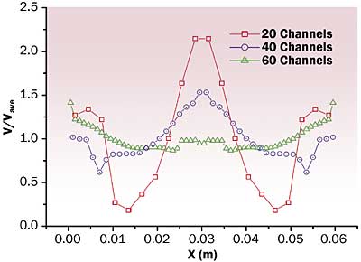
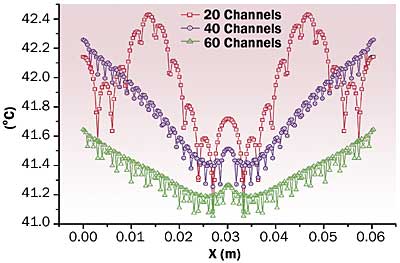
For the purposes of this article, a conventional cold plate is defined as one in which coolant channels are parallel and run from one side of the cold plate to the other. This can also include cases in which coolant channels turn back and forth across the face of the heat source(s). Maldistribution of flow can be significant. Lu, Yang and Wang [3] simulated 60 x 64 mm cold plates with channels 1 to 3 mm wide. Figure 1 shows velocity and temperature distributions at 1 m/s. With 20 channels 3 mm wide, variations in velocity and temperature are much greater than with 60 channels 1 mm wide.
Figure 1a. Velocity distribution at 1.0 m/s [3].
Figure 1b. Temperature distribution at 1.0 m/s [3].
Manifold Flow Distribution
Improvement of the conductance of cold plates has been studied but new designs have seldom been implemented. Harpole and Eninger [4] proposed a manifold microchannel in which alternate inlet and outlet channels guided flow in and out of parallel channels. In their case, the optimum dimensions were quite small. Manifold channel spacing was 333 �m, fin height 167 �m and channel width 7 to 14 �m, with the ratio of fin thickness to channel width from 0.5 to 1.0, significantly smaller than dimensions considered practical for fabrication in copper.
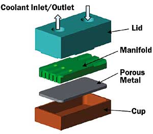
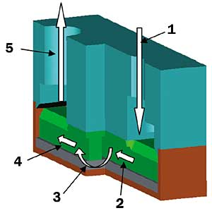
Manifolding has appeared in recent commercial products. Valenzuela and Jasinski [5] describe a normal flow cold plate (NCP) with alternating inlet and outlet manifold channels approximately 1 mm wide. Figure 2 shows a cutaway view of the NCP. The heat transfer matrix is quite thin but not described in detail. Effectiveness values of 0.8 at low flow rates and 0.6 at high flow rates were demonstrated. North and Cho [6] tested an assembly with a multistage manifold, as shown in Figure 3. Coolant enters the inlet port (1), is distributed to a manifold inlet channel (2), then flows the short path through the heat transfer matrix (3) into the adjacent outlet channel (4) and finally through the outlet port (5).
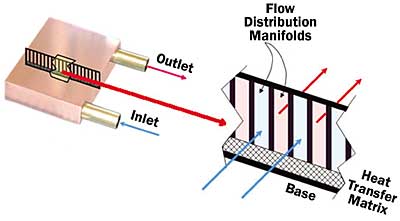 |
Figure 2. Normal flow cold plate (NCP) and manifold structure [5].
Figure 3a. Powdered metal cold plate (PCMP) assembly [6].
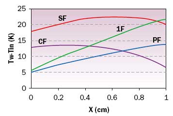
Figure 3b. Coolant flow path [6].Patterson et al. [7] considered four possible arrangements for multilevel flow: single level flow (1F), parallel flow (PF), counter flow (CF) and series flow (SF), shown in Figure 4. Their goals were reduction of both average wall temperature and wall temperature variation. Results with silicon and water at an inlet velocity of 1 m/s are shown in Figure 5. While series flow achieves good uniformity, the wall temperature rise is high. The counter flow arrangement provides low and uniform values of wall temperature rise.
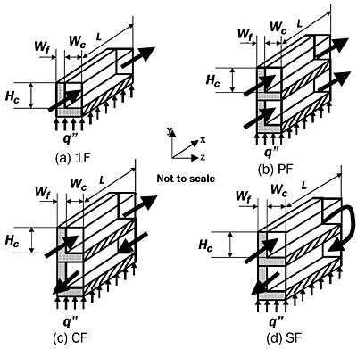 |
Figure 4. Flow arrangements [7].
Figure 5. Wall temperature distribution [7].
Nontraditional Heat Transfer Surfaces
Heat transfer surfaces other than parallel plate fins have also emerged. North and Cho [6] described a porous metal heatsink in which spheroidal particles are bonded together, shown in Figure 6. Nominal particle diameters were 274, 325 and 537 �m. Prechtl and Kurtz [1] presented a microstructured fabrication process in which etched layers were joined together to form a multilayer heatsink, as shown in Figure 7. The resulting channels were 400 x 600, 200 x 300 and 100 x 200 �m.
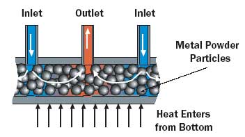 |
Figure 6. Powdered metal cold plate (PCMP) heat transfer matrix [6].
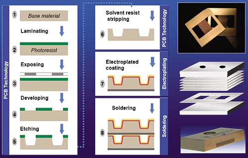 |
Figure 7. Microstructured cold plate fabrication process [1].Muller and Frechette [8] presented a comprehensive numerical study of manifold microchannel heatsinks. With copper and water, using 1 cm2 as the reference area, a thermal conductance of 15.5 W/K could be achieved with 0.005 W pumping power, significantly higher performance than achieved to date. A zigzag fin configuration was introduced, which could lead to even further improvement in performance.
Conclusions
A complete evaluation of cold plate performance requires measurement of flow rate, thermal resistance and pressure drop. Flow rate and thermal resistance for cold plates of different size must be normalized to a unit surface area, traditionally 1 cm2. Figure 8 shows normalized thermal resistance and pressure drop as functions of volume flow rate per unit area for a normal flow cold plate [5]. At the lowest flow rate, effectiveness is about 63%, corresponding to NTU = 1, the optimum value for fixed pressure drop [2]. Small differences in pressure drop at different values of heat flux reflect changes in fluid properties with temperature.
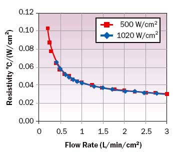 |
Figure 8a. Ultra high flux NCP thermal performance [5].
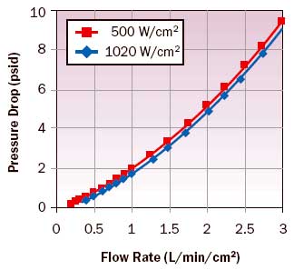 |
Figure 8b. Ultra high flux NCP hydraulic performance [5].In air cooling, nonoptimized heatsinks were adequate until quite recently. The current need for minimization of noise, fan power, heatsink volume and weight have forced optimized designs into production. As a result of volume production, manufacturing techniques such as soldered stacked fins have seen significant reductions in cost. Manufacturing techniques, which allow variation of both the manifold and coolant channel dimensions will permit the effectiveness of the cold plate to be optimized. Once water cooling becomes mainstream, the dual expectations of designs moving closer to optimized values and reduction of manufacturing cost through volume are reasonable.
Acknowledgments
The author wishes to thank Olaf Kurtz of Atotech, George Meyer of Thermacore and Javier Valenzuela of Mikros for information about their products.
References
- Prechtl, P., and Kurtz, O., “Efficient Liquid Cooling Technologies for Computer Systems”, Proceedings of the IMAPS Advanced Technology Workshop on Thermal Management, Palo Alto CA, October 2004.
- Copeland, D. W., “Fundamental Performance of Heatsinks”, ASME Journal of Electronic Packaging, Vol. 125, No. 2, June 2003, pp. 221-225.
- Lu, M.-C., Yang, B.-C., and Wang, C.-C., “Numerical Study of Flow Maldistribution on the Flow and Heat Transfer from Multi-Channel Cold Plates”, Proceedings of the 20th IEEE Semi-Therm Symposium, San Jose CA, March 2004, pp. 205-212.
- Harpole, G. M., and Eninger, J. E., “Micro-Channel Heat Exchanger Optimization”, Proceedings of the 7th IEEE Semi-Therm Symposium, Phoenix AZ, February 1991, pp. 59-63.
- Valenzuela, J., and Jasinski, T., “High Heat Flux Cooling with a Normal Flow Cold Plate (NCP), Thermal Management of Electronics Summit 2004, Natick, MA, August 2004.
- North, M. T., and Cho, W.-L., “High Heat Flux Liquid-Cooled Porous Metal Heat Sink”, Proceedings of Interpack ’03, ASME paper IPACK2003-35320, Kaanapali HI, July 2003.
- Patterson, M. K., Wei, X., Joshi, Y., and Prasher, R., “Numerical Study of Conjugate Heat Transfer in Stacked Microchannels”, Proceedings of ITherm 2004, Las Vegas NV, June 2004, pp. 372-380.
- Muller, N., and Frechette, L. G., “Optimization and Design Guidelines for High Flux Micro-Channel Heat Sinks for Liquid and Gaseous Single-Phase Flow, Proceedings of ITherm 2002, San Diego CA, May-June 2002, pp. 449-456.

