Many readers of ElectronicsCooling are probably familiar with the use of fin efficiency formulas to estimate the thermal resistance of the commonly used parallel plate fin heat sink. Given the heat transfer coefficient, h, acting on a fin and the dimensions of the fin, the thermal resistance of an individual fin is given by:
 |
where Af and η are the surface area and thermal efficiency of the fin. The formula for the efficiency of a straight fin of uniform cross-section is straightforward and may be found in a standard heat transfer textbook [1]. The overall convective thermal resistance of a straight fin heat sink comprised of a number of fins is then given by:
 |
where Nf is the number of fins and Rb is the convective thermal resistance associated with the exposed base area, Ab, between two fins. The thermal resistance, Rb, is given by:
Those unfamiliar with estimating the thermal resistance of straight fin heat sinks may find a more detailed discussion of the subject in an earlier article in ElectronicsCooling [2].
 |
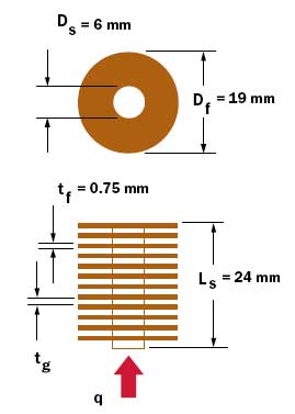
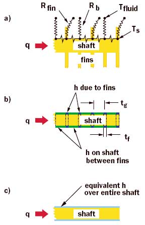
Figure 1. Example of a stacked radial fin heat sink configuration.The focus of the present Calculation Corner is on the use of an equivalent heat transfer coefficient to calculate the thermal resistance of a compound fin or a fin upon fin heat sink configuration. An example of one such configuration is the stacked radial fin heat sink shown in Figure 1. As shown in Figure 2a the convective thermal resistance of the radial fins and the exposed shaft surface areas between the fins act thermally in parallel. If the shaft was a perfect thermal conductor with infinite thermal conductivity, the shaft temperature, Ts, would be uniform along the length and the thermal resistance from the bottom of the stud to the cooling medium could be calculated using equation (2). Of course for materials with finite thermal conductivity (e.g., aluminum or copper) there will be a temperature gradient along the shaft.
 |
Figure 2. Alternative model approaches: a) discrete thermal resistances, b) multiple differential equations, c) equivalent h approach.So, not only will the radial fins exhibit a thermal efficiency, but so will the shaft to which they are attached. One could attempt to set up and solve the differential equations governing convection and conduction for each region of the shaft. This would result in a differential equation for each section of the shaft with an appropriate heat transfer coefficient applied as shown in Figure 2b. Setting up and solving these equations would be a laborious task and at best would result in a lengthy and complex algebraic result. More likely one would set up and solve a finite difference model or set up and solve the problem using a commercially available thermal code.
Fortunately, there is an even simpler approach, which generally gives very good results. This is approach is to apply an overall equivalent heat transfer coefficient to the total lateral surface area of the shaft (i.e., As = π DsLs ) as shown in Figure 2c. Setting Ro in equation (2) equal to 1/heAs, equation (2) may be reformulated to provide an equation for the equivalent heat transfer coefficient:
For the configuration under consideration Rb is based upon the exposed shaft lateral surface area between two fins.
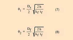
In order to determine the value of Rf using equation (1) it is necessary to determine the thermal efficiency of a radial fin [3]. This is given by:
 |
 |
where kf and tf are the thermal conductivity and the thickness of the fin, Df is the outer diameter of the fin, Ds is the inner diameter of the fin (which of course is equal to the diameter of the shaft), and h is the heat transfer coefficient acting upon the fin. The functions I0 and K0 are zero order modified Bessel functions of the first and second kind respectively, and I1 and K1 are first order modified Bessel functions of the first and second kind respectively. These functions are available for numerical calculation in commonly used spreadsheet programs as well as symbolic algebra programs. For those readers unfamiliar with or intimidated by Bessel functions, graphs, which may be used to find the thermal efficiency of radial fins, are available in many heat transfer textbooks [1].
It is then necessary to determine the thermal efficiency, ηs, of the shaft using:
 |
At this point the overall convective thermal resistance of the stacked radial fin heat may be calculated using:
 |
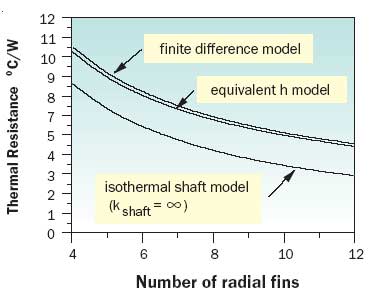
To illustrate the effectiveness of this approach, example calculations were performed for an aluminum radial stacked fin heat sink with the dimensions shown in Figure 1. For purposes of calculation a convective heat transfer coefficient of 50 W/m2-K was applied to both the fins and the exposed shaft surfaces between the fins. The results for the overall thermal resistance are shown in Figure 3 for 4 to 12 fins. Results are also shown based upon a finite difference conduction analysis model taking into account the convective heat transfer from the radial fins and the exposed shaft areas along with the thermal conduction drop along the shaft. As may be seen the overall thermal resistance values calculated using the equivalent h approach were only slightly lower than the results of the more accurate finite difference conduction analysis. The difference between these two models was less than 3% over the entire range of calculations.
 |
Figure 3. Comparison of thermal resistance values calculated using three different models.As demonstrated with this example, using an equivalent h approach offers a relatively easy and effective means of estimating the thermal resistance of a compound fin heat sink structure. This method is not limited to the geometry chosen for the example and may easily be extended to structures with rectangular geometries.
References
- Incropera, F.P., Fundamentals of Heat and Mass Transfer, John Wiley and Sons, New York, NY, 1985.
- Simons, R.E., “Estimating Parallel Plate-Fin Heat Sink Thermal Resistance,” ElectronicsCooling, Vol. 9, No. 1, 2003, pp. 8-9.
- Gardner, K.A., “Efficiency of Extended Surfaces,” ASME Transactions, Vol. 67, 1945, pp. 621-631.


