Introduction
Over the past few years many people in the electronics industry have become concerned with the increases in heat density at both the chip and module level of packaging. This trend is not new and has been with us since the days of bipolar chips. As can be seen in Figure 1, the heat flux associated with bipolar circuit technologies steadily increased from the beginning and took off in the 1980’s requiring the use of indirect liquid cooling via water-cooled cold plates at the module level. There was a brief respite, and a return to air-cooling with the transition to CMOS circuit technologies in the 1990’s; however, the demand for increased packaging density and performance reasserted itself and heat flux is again increasing dramatically. This has prompted many to ask what are the practical limits of air-cooling and when is it necessary resort to some form of liquid cooling?
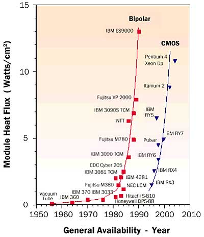 |
Figure 1. Evolution of module level heat flux in high-end computers.There are no simple answers to these questions. The practical air-cooling limit will differ for each application scenario and depends upon the package configuration, the desired chip temperature, cooling air temperature, the volume available for a heat sink, air flow and pressure drop available, acoustic constraints, and other factors. This article seeks to provide insight as to the relative performance of air-cooling in comparison with liquid cooling options. Both indirect and direct liquid cooling options are considered. Indirect liquid cooling options include water-cooled cold plates applied at the module level and micro cold plates attached at the chip level. Direct liquid cooling options include forced convection water or fluorocarbon cooling with micro heat sinks attached to the chips, jet impingement with water or fluorocarbon on the bare chip surface, or fluorocarbon spray cooling of the chips.
Calculations focused on comparing cooling performance capability with these different options were performed based upon a multi-chip module (MCM) configuration of four 12.25 x 12.25 mm chips on a 42.5 x 42.5 mm substrate as shown in Figure 2. The calculations were based upon limiting the height of the module package plus cooling device to less than 89 mm so as to fit into a rack drawer 2 EIA (Electronics Industry Association) units high. The maximum chip temperature was assumed to be 85°C and the coolant inlet temperature, 25°C.
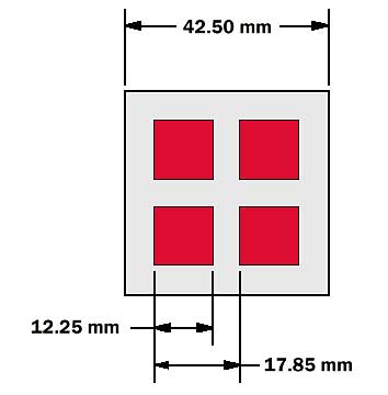 |
Figure 2. Chip and module dimensions.
Air Cooling
A recent paper by Saini and Webb [1] considered the problem of heat rejection limits of parallel plate fin heat sinks for a single chip package in a “desktop” computer application. Calculation results were reported based upon a 16 x 16 mm heat source and a temperature difference of 35°C from the heat source to inlet air. The maximum allowable heat load reported was 95.2 W corresponding to a maximum allowable uniform chip heat flux of 37.2 W/cm2.
The results reported in this article focused on determining the maximum uniform heat flux that the authors consider achievable for the assumed configuration with a parallel plate fin heat sink as shown in Figure 3. The base of the heat sink was assumed to be a vapor chamber with dimensions of 80 x 80 x 4 mm. Both aluminum and copper fins with a thickness of 0.381 mm and height of 60 mm were considered. Thermal interface unit resistances of 10 and 5°C-mm2/W, representing a thermal paste or solder interface respectively, were applied between each of the chips and the base of the vapor chamber. Analysis of the vapor chamber spreading resistance to the base of the fins, including the thermal resistance across the silicon chip and the interface, revealed an overall thermal resistance (Rc-hs) per chip of 0.267°C/W for thermal paste and 0.20°C/W for a solder joint.
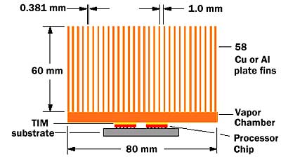 |
Figure 3. MCM air cooled heat sink configuration.Analysis of the heat sink thermal resistance and pressure drop was performed using equations from references [2] and [3]. Air flow performance was based upon two high performance radial blowers operating in parallel to provide a volumetric flow rate of 0.0217 m3/s (45.9 CFM) with a pressure drop of 141.4 Pa (0.567 in. of H2O) through the fins. This resulted in a heat sink thermal resistance (Rhs) at the module level of 0.10°C/W for aluminum fins and 0.069°C/W for copper fins.
Keeping in mind that we are dealing with four chips on a module, using these values in Equation (1)
 |
provides the maximum allowable uniform chip heat fluxes. For the configuration analyzed, the maximum allowable chip heat flux was found to range from 60 to 84 W/cm2. In an actual application not all of the air flow from the blowers could be ducted into the MCM heat sink. Some of the air flow would have to be diverted to other air-cooled components within the drawer, thereby reducing the maximum allowable chip heat flux.
Indirect Liquid Cooling
Indirect liquid cooling schemes are denoted by the presence of distinct physical barriers between the chip and the liquid. Several possible implementations are illustrated in Figure 4. The most conservative implementation is to attach a separable cold plate to a lidded module (Figure 4a). When greater thermal performance is desired, the interface between the cold plate and the module can be eliminated by integrating the cold plate with the module (Figure 4b). Taking the concept to the limit, chip-scale high performance cold plates of the type discussed in Reference [4] can be attached directly to the chips (Figure 4c).
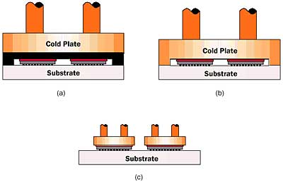 |
Figure 4. Indirect liquid cooling schemes: (a) separable module cold plate, (b) integral module cold plate, and (c) individual chip-scale cold plates.An analysis assumption common to all three indirect cooling schemes considered here is that the liquid volumetric flow is in proportion to the heat dissipated at a ratio of 6.31×10⁻⁸ m3/s per watt (or 1 gpm per 1 kW). Single phase convection heat transfer is also assumed. Under these conditions, the module cold plate thermal performance is estimated to be as low as 12.8°C-mm2/W. This cold plate is assumed to have an active area of 42.5 x 42.5 mm and channel widths approaching the microchannel scale of less than 0.2 mm. As was the case for the air cooled module, a chip-to-lid paste unit resistance of 10°C-mm2/W is assumed for the module level cold plate schemes. Additionally, a lid-to-cold plate unit resistance of 25°C-mm2/W (a PAO oil interface with an average bond line of 0.0045 mm) is assumed for the separable cold plate. The performance for the individual chip-scale cold plate is given in [5] at a combined 9°C-mm2/W for interface and cold plate. The interface is assumed to be metal (i.e., solder) and the cold plate is assumed to have microchannels less than 0.1 mm in width. Under these conditions, the chip heat removal capability for a chip junction to liquid inlet temperature difference of 60°C is 227, 320, and 397 W/cm2 for the separable module cold plate, integral module cold plate, and individual chip-scale cold plate configurations, respectively.
Direct Liquid Cooling
Direct liquid (immersion) cooling brings the coolant in direct contact with the back of the chip. Historically, the coolant considered was a dielectric (e.g., fluorocarbon coolants or FCs) primarily because it would also be in direct contact with the chip interconnects and substrate top surface metallurgy (TSM). For this exercise, it is assumed that water can be brought in direct contact with the back of the chip. Obviously a seal or barrier preventing water from contacting the interconnects or TSM is needed. For now, it is assumed that such a seal/barrier is technically feasible.
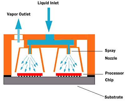 |
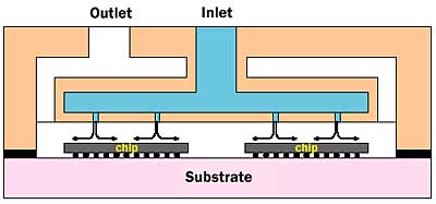
Figure 5. Direct liquid spray cooling of chips on an MCM.For the dielectric cooling cases, a few different options may be considered. For example, droplets of a dielectric coolant may be sprayed on the chip surface as shown in Figure 5. Based upon values reported in the literature [6, 7] spray cooling with a fluorocarbon liquid (i.e., FC-72) is capable of supporting heat fluxes up to 50 to 60 W/cm2 while limiting chip junction temperatures to 85°C. Jet impingement of a dielectric liquid on the chip surface may also be considered (Figure 6). Researchers have reported chip heat fluxes approaching 120 W/cm2 and a chip to liquid temperature difference of 60°C while cooling a 6 x 6 mm silicon chip with a single jet of FC-72 liquid at a flow rate of 2.2 x 10⁻⁴ m3/s [8]. It is expected that for the chip size under consideration here, the same heat flux and temperature difference could be achieved with four jets and a liquid flow rate per chip of 8.8 x 10⁻⁴ m3/s. Alternatively, the dielectric coolant flow could be directed through a microchannel heat sink attached directly to the chip as shown in Figure 7. As with indirect liquid cooling, single phase convection heat transfer is assumed. It is also assumed that a metal chip-to-heat sink interface of 2.5°C-mm2/W is the best achievable for the heat sink attach.
Figure 6. Direct liquid jet impingement.
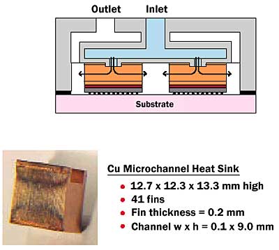 |
Figure 7. Direct liquid cooling with a dielectric coolant and a microchannel heat sink attached directly to the chip.Ultimately, given that an adequate chip to liquid seal can be provided, direct jet impingement of water on the back of the chip may be considered. For this case a recently published correlation [9] for multiple jets is used to predict water jet impingement cooling performance.
For these various options, the chip heat removal capability for a 60°C chip to liquid inlet temperature difference is estimated to be 60, 120, 300, and 460 W/cm2 for spray cooling, dielectric jet impingement cooling, forced convection dielectric cooling with a heat sink attached to the chip, and water jet impingement, respectively.
Conclusion
A comparison of the heat removal capability in terms of chip heat flux for the module cooling concepts discussed is shown in Figure 8. These performances levels should not be thought of in absolute terms as the application conditions that constrain performance are themselves not absolute. In the case of air cooling, one can always consider a larger heat sink and/or more air flow to remove more heat from the chip or module. Of course, this would be at the expense of an overall increase in package volume and increased acoustic noise, both of which are highly undesirable. Instead, these heat removal capabilities should be considered in relative terms. Indirect liquid cooling offers the capability of heat removal rates two to four times that of air cooling. The traditional direct liquid cooling schemes, in the form of FC spray cooling or FC jet impingement, do not approach the performance of indirect liquid cooling. The non-traditional indirect liquid cooling schemes, using an FC with chip-scale heat sink or water jet impingement, are comparable to indirect liquid cooling. Direct water jet impingement appears to be slightly better than the best indirect liquid cooling possible (i.e., a chip-scale cold plate attached directly to the chip).
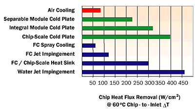 |
Figure 8. Comparison of heat removal capability.From a technology point of view, it may be possible to push performance beyond what has been shown. One possible extension to direct liquid jet impingement cooling is to provide extended surfaces on the back of the chip in combination with the jet impingement flow. For now, it appears that there are several technologies capable of cooling chips and modules well beyond the practical limits of air cooling – not a moment too soon.
References
- Saini, M., and Webb, R.L., “Heat Rejection Limits of Air-Cooled Plane Fin Heat Sinks for Computer Cooling,” IEEE Trans. Components and Packaging Technologies, Vol. 26, No. 1, 2003.
- Simons, R.E., “Estimating Parallel Plate-Fin Heat Sink Thermal Resistance,” ElectronicsCooling, Vol. 9, No. 1, 2003.
- Simons, R.E., “Estimating Parallel Plate-Fin Heat Sink Pressure Drop,” ElectronicsCooling, Vol. 9, No. 2, 2003.
- Copeland, D., “Review of Low Profile Cold Plate Technology,” Electronics Cooling Magazine, Vol. 11, No. 2, May, 2005, pp. 14-18.
- Colgan, E.G., Furman, M., Gaynes, M., Graham, W., LaBianca, N., Magerlein, J.H., Polastre, R.J., Rothwell, M.B., Bezama, R.J., Chaudhary, R., Marston, K., Toy, H., Wakil, J., Zitz, J., and Schmidt, R., “A Practical Implementation of Silicon Microchannel Coolers for High Powered Chips,” Proceedings of the 21st Annual IEEE Semiconductor Thermal Measurement and Management Symposium, San Jose, CA, USA, March 15-17, 2005, pp. 1-7.
- Pautsch, G., and Bar-Cohen, A., “Thermal Management of Multichip Modules with Evaporative Spray Cooling,” Advances in Electronic Packaging, ASME EEP- Vol. 26-2, 1999, pp. 1453-1461.
- Lin, G., and Ponnappan, R., “Heat Transfer Characteristics of Spray Cooling in a Closed Loop,” Intl. Jour. of Heat and Mass Transfer, 46, 2003, pp. 3737-3746.
- Chrysler, G.M., Chu, R.C., and Simons, R.E., “Jet Impingement Boiling of a Dielelectric Coolant in Narrow Gaps,” IEEE Trans., CPMT-A, Vol. 18, No. 3, 1995, pp. 527-533.
- Campbell, L.A., Ellsworth Jr., M.J., Iyengar, M., Simons, R.E., and Chu, R.C., “Experimental Investigation of the Heat Transfer Performance of Arrays of Round Jets with Sharp-Edged Orifices and Peripheral Effluent; Convective Behavior of Water on a Heated Silicon Surface,” Proceedings of the 2005 ASME Summer Heat Transfer Conference, San Francisco, CA, USA, July 17-22, 2005.

