| Nomenclature |
|
| Q | Heat load (W) |
| COP | Coefficient of Performance |
| I | Electrical current (Amps) |
| T | Temperature (°C) |
| R | Electrical resistance (Ohms) |
| Z | TE Figure of Merit (1/K) where Z = α2 / (ρ λ) |
| Greek Letters | |
| Δ | Change in value |
| θ | Thermal resistance (°C/W) |
| ρ | Electrical resistivity (Ohm-cm) |
| α | Seebeck coefficient (V/K) |
| λ | Thermal conductivity (W/mK) |
| Subscripts | |
| SA | Sink to Ambient |
| S | Sink |
| CA | Case to Ambient |
| p | P type thermoelectric material |
| n | N type thermoelectric material |
| c | TEC cold side |
| h | TEC hot side |
Introduction
The microelectronics industry is reaching the limits of traditional air cooling for many applications. The continuing trends of smaller active portions of the die and higher heat dissipation lead to higher watt densities and larger thermal interface losses. This forces the thermal designer to utilize more and more efficient heat sinks because a significant portion of the die to ambient ΔT is consumed by interface and spreading losses. This article provides a simple way of assessing the potential benefits of adding optimally designed thermoelectric coolers (TECs) to enhance or augment heat sink performance, whether air or liquid cooled. This article builds upon the work published at recent technical conferences [1, 2, 3]. The solid state design of the TEC affords a compact, highly reliable means of addressing the issues faced by many thermal designers. For the thermoelectrically enhanced heat sink, the TEC provides an effective negative thermal resistance in the thermal path of the high-powered device, thus offsetting interface and spreading losses. Obviously, this negative thermal resistance is not free, requiring additional system power and costs. However, if implemented correctly, both of these can be managed and the TEC can become an effective addition to the thermal designer’s toolbox.
TEC Optimization – a Must
Performance of a TEC is governed by a well-known set of equations that are covered in many different references [4, 5, 6, 7, 8]. As such, a detailed derivation and presentation of the governing equations for thermoelectrics will not be presented. Instead, only those equations pertinent to the proper optimization of the thermoelectric device will be covered.
An experienced thermoelectrician may ask, “What is the optimum thermoelectric design?” (That is, what TEC design provides the minimum power consumption.) For a given thermoelectric element geometry (length and cross section), an optimum current exists based on the hot and cold side temperatures of the thermoelectric (Th – Tc respectively) and the thermoelectric material properties. This optimum current is given by:
 |
Likewise for a given set of operating temperatures, the maximum possible (optimum) COP for a thermoelectric device can be determined based on the thermoelectric material properties:
 |
In most applications, especially in applications where poor heat sinking is provided, it is extremely important to use TECs that operate near this optimum COP. Selection and use of a non-optimum TEC will result in performance significantly poorer than that of an optimum TEC and, in many cases, performance poorer than the baseline performance without a TEC [9, 10, 11]!
For a given thermoelectric material, Equation 2 can be used to plot the maximum COP as a function of the thermoelectric element ΔT (Th-Tc). This is illustrated in Figure 1 using high performance, commercially available Bismuth Telluride (Bi2Te3) thermoelectric materials. As can be seen from the curve, COPs in excess of one are possible with today’s best commercially available bulk materials for ΔT’s less than about 30°C. In addition, the COP climbs significantly for systems designed to run optimally at even lower ΔT’s.
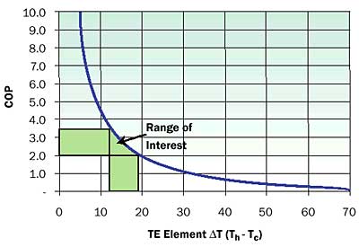 |
Figure 1. Theoretical optimum (maximum) COP vs. ΔT.In practice, many casual users of thermoelectrics select a module from a manufacturer’s web page and operate it near its rated maximum current. This approach potentially results in significantly degraded performance as illustrated in Figure 2, which shows a plot of COP as a function of the percentage of maximum rated current (I/Imax).
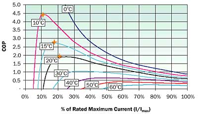 |
Figure 2. COP as a function of current.The peak COP for each of the curves coincides with the single curve of Figure 1. Each curve represents a TEC optimized for that particular ΔT and then operated at various different currents from 0 to Imax. Notice that, for a given curve, the COP drops significantly as the TEC is operated “off-optimum”, especially for ΔT’s less than 30°C.
In addition, examination of Figure 2 shows that the current required to produce high COPs is a very low percentage of the TEC rated maximum current (10 – 15% of Imax). In other words, the TEC must pump the desired heat while “idling” at a low percentage of Imax in order to achieve the high COPs.
Demonstrating the Thermoelectrically Enhanced Heat Sink Concept
The easiest way to demonstrate the concept of the thermoelectrically enhanced heat sink is to simply walk through a typical example comparing a traditional heat sink configuration with one incorporating thermoelectrics. Figure 3 provides the resistor network and typical numbers for a system designed based on the following assumptions.
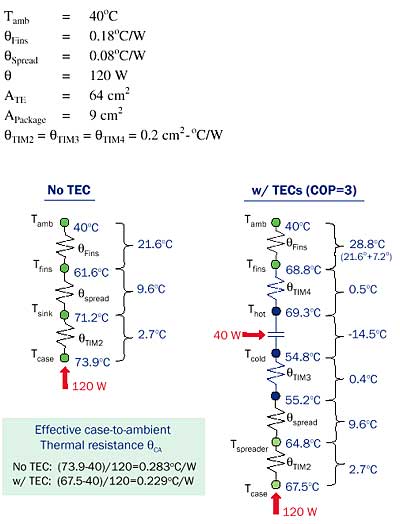 |
Figure 3. Typical thermal resistor networks with and without a TEC.As can be seen from the resistor networks with and without a TEC, adding the TEC adds additional thermal interfaces but also provides a negative ΔT in the thermal path.
For the no-TEC case, we start with a CPU heat load of 120 W from a 30 x 30 mm CPU package. The package is mounted to a heat sink using thermal grease with a TIM2 thermal resistance of 0.2 cm2-°C/W. The sink to ambient thermal resistance is broken down into two components; a spreading component due to the small heat input area, and the fin to ambient component as shown in Figure 3. The reason for doing this will be evident when the TECs are added. (When the TECs are added, we can use a simpler heat sink, one designed for a uniform heat input, and this spreading in the heat sink is not necessary.)
As you may note from simple resistance calculations, case temperature for the no-TEC case is determined to be just less than 74°C. This equates to a case to ambient thermal resistance of θCA = 0.283°C/W.
For the With-TEC case, we assume the TECs will operate with a COP of 3. For practical applications of CPU cooling, the COP will likely be between 2 and 3.5, corresponding to TEC Δ T’s between 12 and 20°C. For COPs greater than 3.5, sufficient ΔT is simply not generated by the TEC to offset the additional interface and heat sink rise and still provide measurable performance improvement. For COPs less than 2, considerable additional input power must be supplied and dissipated by the heat sink.
For the 120 W CPU heat dissipation, a COP of 3 equates to a TEC input power of 40 W and a TEC ΔT of about -14.5°C. This 40 W must be dissipated by the heat sink in addition to the CPU heat load, thus raising the heat sink temperature by 7.2°C. In this example, we assume we have multiple TECs that cover the heat sink area (total TEC area of 64 cm2). As such, the heat sink has a much larger heat input area compared to the no-TEC case thus eliminating the need for a thick copper base plate or embedded heat pipe(s) to spread the heat. The need for spreading is moved from the heat sink to the cold side of the thermoelectrics. This cold side spreader could be a heat pipe assembly, vapor chamber, or solid copper spreader. There obviously are cost, performance, and weight tradeoffs for each of these. For this example a generic spreading resistance of 0.08°C/W was assumed.
From Figure 1, we determine that an optimally designed TEC operating at a COP of 3 would have a ΔT of about -14.5°C. With the TEC, the case temperature drops from 73.9°C to 67.5°C, a reduction of approximately 6.4°C, resulting in a 19% reduction in θCA for the 120 W case. Note that the TEC actually operated with a 14.5°C negative Δ T, yet the case temperature was reduced by only 6.4°C. More than half of the negative ΔT from the TEC must be used to offset the additional interface losses and additional rise in heat sink temperature due to the TEC input power.
 |
Also, it should be noted that for the baseline system without the TEC, the 0.283°C/W thermal resistance is a constant with respect to heat load. For the TEC, the 0.229°C/W is not a constant with respect to heat load and accurately represents the thermal resistance for the 120 W heat load only. This will be evident when we examine actual data.
There are several key items that should be noted when considering incorporating a TEC. First of all, the TEC should operate near its maximum (optimum) COP for the Δ T chosen. As shown in Figure 2, off-optimum operation results in significantly higher TEC power consumption (lower COP). This in turn will result in a larger ΔT across the hot side thermal interface and a larger additional rise in heat sink temperature, thus reducing the net gain from the negative ΔT from the TEC. In addition, for the same COP and thus the same input power, an off optimum TEC will not achieve the same ΔT, thus even further reducing the ΔTnet. The performance penalty for selecting non-optimum TECs and running them off-optimum is severe!
Second, if one studies the results of the analysis shown in Figure 3, one can recognize there will be cases when a TEC should not be used – even if it is optimally designed. Even if we assume an optimally designed TEC that behaves according to Figure 1, if the heat sink performance is poor, the additional rise in heat sink temperature ( ΔTsink) will offset more of the negative ΔT from the TEC. For example, if we had a very poor heat sink with a fin to ambient thermal resistance of 0.3°C/W instead of 0.18°C/W (with all other parameters in the example kept the same), the additional rise in temperature of the heat sink due to the necessary dissipation of the TEC power would increase from 7.2 to 12.0°C (0.3°C/W x 40 W). The net gain from adding the TEC drops to only -1.6°C. This small gain would likely not justify the added cost of adding the thermoelectrics. Using Figure 1 and the analysis example in Figure 3 becomes an easy way to evaluate the best performance from a TEC to see whether it is advantageous to incorporate the TEC and to estimate the thermal performance improvement possible.
Finally, keep in mind these calculations were performed at the design power heat dissipation at the maximum ambient conditions. Typically, the processor would not operate for prolonged periods at these extreme conditions especially in a desktop application. When the processor heat dissipation is less than 120 W or when the ambient is less than the maximum, the realized TEC COP can be significantly greater, rising exponentially as the required TEC ΔT is decreased (see Figure 1). COPs as high as 5, 10, 15 or more would be likely under typical operating conditions when only small ΔTs would be required by the TEC in order to maintain the maximum junction temperature below its specification. More details of this off-peak operation are provided in [1]. Likewise, operating the TEC at a constant input power under these non-peak conditions offers the opportunity for significant reductions in fan speed with favorable acoustic benefits.
TEC Requirements
In the description of the TE enhanced heat sink concept, multiple TECs and a large spreader were utilized. For four TECs pumping 120 W, each TEC must pump 30 W. Using the generalized thermoelectric performance curve [12] given in Figure 4, we can get an idea of the type of TEC required. For a COP of 3 operation, our optimum Δ T was 14.5°C (Figure 1). For a typical TEC with a ΔTmax of around 68°C, the ratio of ΔT/ ΔTmax is about 0.21. From Figure 4, we can see for optimum (lowest power) operation, Q/Qmax is approximately 0.17. Therefore, for a 30W TEC heat load per TEC, the Qmax for each TEC should be approximately 30/0.17 = 176 W.
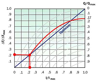 |
Figure 4. Generic thermoelectric performance curve.In addition, the four TECs and a large cold side spreader add cost and weight to the system. A single TEC with partial spreading of the heat prior to the TEC and additional spreading between the TEC and heat sink could offer some interesting performance/cost tradeoffs. However, if the entire heat from the CPU were pumped by a single TEC, the Qmax of that single TEC would need to be approximately 700 W (120/0.17)!
Pathways to High Watt Density Thermoelectrics
Most commercial TECs have Qmax values of 70W or less for a 40 mm square TEC. For a constant cross sectional area, the Qmax of a TEC is inversely proportional to the thermoelectric element height. In other words, the Qmax of a TEC can be doubled by cutting the element height in half. Therefore, High Watt Density (HWD) TECs are achieved by making the thermoelectric elements very short and by minimizing the spacing between individual thermoelectric elements so that more elements can be fit in the same area.
Material Requirements
Crystal growth techniques, such as the Bridgman method, are typically employed for producing the Bismuth Telluride thermoelectric materials. The material structure produced from these growth methods imposes significant limitations on the thermoelectric element dimensions due to poor manufacturing yields. This prevents thermoelectric elements from being made very short. Wafers cut from these ingots break during processing due to the weak bonds holding adjacent crystals together. New fine-grain micro-alloyed Bi2Te3 materials don’t suffer from this element geometry limitation and can offer higher performance as well [13]. Figure 5 shows a prototype 40 mm square device with a Qmax in excess of 650 W. Therefore, with the new material format, the HWD thermoelectric devices necessary to enable CPU applications become practical.
 |
Figure 5. Prototype 40 mm square TEC with Qmax>650W.
Example Performance
Figure 6 shows actual performance of a thermoelectrically enhanced air cooled heat sink. In these tests, a single 40 mm square TEC with a small, simple 40 x 40 x 4 mm copper spreader were used. In this case, the heat load was produced from a thermal test chip supplied by a major chip manufacturer. Heat loads from this Thermal Test Vehicle (TTV) were varied from 50 – 110 W. As can be seen from the graph, significant performance improvements are possible, even with a single HWD TEC. At a COP of 2, the baseline case to ambient thermal resistance dropped from 0.26 to 0.20°C/W, a 23% reduction, for a heat load of 110 W. Model predictions, also shown on the graph matched actual performance quite well.
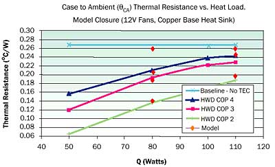 |
Figure 6. Actual performance for air cooled TE enhanced heat sink.
Conclusions
New HWD thermoelectric technology, enabled by micro-alloyed thermoelectric materials, offers an opportunity to provide significant extension of existing air cooled and liquid cooled heat sinks. The TEC, when properly designed can provide a variable negative thermal resistance in the CPU thermal path. This variable negative thermal resistance can be used to enhance the performance, reduce acoustics or allow the CPU to operate at cooler temperatures.
References
- Bierschenk, J.L., Johnson, D.A, “Extending the Limits of Air Cooling using Thermoelectric Enhanced Heat Sinks”, Itherm 2004, pp.679-684.
- Saucic, I., “Thermoelectric & Phase Change Technology Building Block with Application to CPU Cooling,” Intel Technology Symposium 2004, Sept 7-9, 2004.
- Bierschenk, J.L., Johnson, D.A., “Advances in High Watt Density (HWD) Thermoelectrics and Implications for CPU Cooling,” IMAPS ATW, 2004.
- Godfrey, S., “An Introduction to Thermoelectric Coolers”, ElectronicsCooling, September 1996.
- Simons, R.E., “Application of Thermoelectric Coolers for Module Cooling Enhancement,” ElectronicsCooling, May 2000.
- Goldsmid, H.J., Electronic Refrigeration, Chapter 1, Pion Limited, London, 1985.
- Rowe, D.M., ed., CRC Handbook of Thermoelectrics, Section A, CRC Press, Boca Raton, Fla., 1995.
- Ioffe, A.F., Semiconductor Thermoelements and Thermoelectric Cooling, Part 2, Chapter 1, Infosearch Limited, London, 1957.
- Phelan, E.P., Chiriac, V.A., Lee, T-Y, “Current and Future Miniature Refrigeration Cooling Technologies for High Power Microelectronics,” IEEE Transactions on Components and Packaging Technologies, Vol. 25, No. 3, 2002, pp 356-365.
- Chu, R.C., Simons, R.E., “Application of Thermoelectrics to Cooling Electronics: Review and Prospects,” 18th International Conference on Thermoelectrics, 1999, pp. 270-279.
- Solbrekken, G.L., Yazawa, K., Bar-Cohen, A., “Chip Level Refrigeration of Portable Electronic Equipment Using Thermoelectric Devices,” Proceedings of InterPack 2003, Paper IPAC2003-35305.
- Marlow Industries, Inc. Web page, Thermoelectric Cooler Selection Process, http://www.marlow.com/TechnicalInfo/themoelectric_cooler_selection_p.ht m
- Lyon, H. B., Jr., “The Marlow Advanced Thermoelectric Materials Program,” Volume 1, Issue 1, Marlow Industries, Inc. Web page article: http://www.marlow.com/AboutMarlow/advanced_materials.htm


