Introduction
In 1995, a typical thermal design engineer was aware that removing heat was not going to get any easier in the next few years. A look back at the past ten years reveals that thermal management remained a challenging field. Fortunately, developments and improvements in thermal management hardware have assisted the electronics packaging community by enabling higher heat fluxes in ever-smaller packaging volumes. In almost every packaging design, the cost of the thermal management hardware must be small compared to the overall system cost. The growth of commercial electronics since 1995, coupled with the need for better cooling, has enabled some thermal management technologies to move from expensive aerospace technologies to costs that are viable for commercial packaging.
This article gives a brief overview of some of the more significant thermal management hardware and tools developed and improved since the beginning of ElectronicsCooling magazine. Recognizing that limitations of both article length and the authors knowledge will result in some omissions, the intent of this article is to highlight some of the most significant thermal management developments in the past decade.
Packaging
The story of packaging in the past decade is tightly coupled to the continuous and rapid development of integrated circuit technology as exemplified by Moore’s Law (i.e., the number of transistors in an IC doubles every 18 months).
Once the integrated circuit was invented, it was an inevitable trend that more and more of the functionality of a given electronic system would be integrated into fewer and fewer chips. The increased functionality led to requirements for greater I/O (input-output) connections and greater power. Packaging, as always, had to satisfy the role of an enabling technology to allow the full performance potential of a semiconductor to be realized in a given application. Package technology experienced dramatic changes to keep pace with these rapid changes in IC functionality. Package technology trends are illustrated in Figure 1.
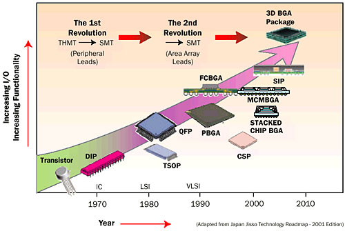 |
Figure 1. Packaging technology trends.
By 1995 surface mount technology (SMT) had displaced through-hole mounting technology (THMT) in most applications. Quad packages with peripheral leads were getting into the 200-300 lead range. PC processor power levels were just hitting 10W and the power levels of the other devices scaled appropriately.
The need for greater numbers of I/O connections promoted the migration to area array packages. The Ball Grid Array (BGA) package, with organic laminate substrates (miniature printed circuit boards) as the electrical distribution medium began to flourish. Unlike the previous generation of leadframe packages, which needed the production of expensive stamping dies to fabricate the leadframe, the BGA could be produced with flexible manufacturing processes: photolithography coupled with numerically-controlled drilling [1, 2].
Once the BGA package was established in the marketplace it was inevitable that flexible manufacturing would allow a proliferation of variants of the basic design. These included multi-chip packages, package with multiple chips and passive components (System-in-Package), flip chips, and stacked chips.
SMT was accompanied by the use of multilayer systems boards with power and ground planes. In a short period of time, thermal engineers learned to take advantage of the system board as a heat spreader to enhance the flow of heat to the ambient air. Thermal considerations led to the use of thermal vias to enhance heat flow through the thickness of both the package laminate and the system board [3]. Further enhancements of BGA package thermal performance were obtained by the use of power and ground planes of increasing thickness. Even greater thermal performance was obtained by the use of heat spreaders or heat slugs incorporated into the package.
The increase of IC I/Os into the range greater than 500 connections led to the replacement of wire bonding as the first-level interconnect by flip chip technology. This resulted in the development of packages with an efficient decoupling of the electrical and thermal functions. In a nutshell: the electrons go down into the system board, and heat goes up into the top of the package, and then directly into a heat sink and the cooling medium. As chip power levels exceeded 100 W, package lids made of composite materials with high-thermal conductivity and coefficients of thermal expansion matched to silicon became necessary. The use of advanced thermal interface materials with stability over many thermal cycles became an essential part of the design.
Thermal Interface Materials
In common air-cooled electronics packaging configurations, the temperature rise across thermal interfaces is frequently one of the largest contributors to the total rise from the junction to ambient air. While thermal interface materials are certainly older than ten years [4], both the number of thermal interface materials available to the designer and the choice of suppliers have greatly increased. The 1995 Semi-Therm exhibitor list contained three interface material vendors, but in the ten years since then, more vendors entered the interface material business, which forced competitive performance and pricing.
Both the design and supplier community in this area now recognize that bulk material conductivity is insufficient for predicting thermal resistance [5,6]. Thermal performance data is now usually reported in terms of an area normalized contact resistance and the test method is usually referenced [7,8]. However, there is still considerable debate about the appropriateness of these standards for the thermal management arena [9]. The past ten years have seen a maturing of the use of phase change coatings to fill in the microvoids, especially useful in applications that do not have a large contact pressure. The melting temperature of the phase change materials have also migrated to values that are compatible with commercial electronics cooling. Figure 2 illustrates typical thermal resistance values for some of the more common interface materials [10]. Note that moving on the chart from the left (bare interface) towards soldered attachment represents significant decreases in thermal resistance. Selecting a proper interface material requires consideration of induced stress, reparability, contact pressure and flatness as well as thermal considerations.
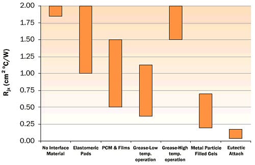 |
Figure 2. Thermal interface materials.
Higher thermal performance materials that contain high conductivity graphite are becoming available with claims of thermal interface resistance in the range of 0.06 cm2 – °C/W [11], putting them in the range of soldered connections, but without the associated residual stresses from assembly. Some of these materials started as government funded research activities for high heat flux applications more than ten years ago and have become available as commercial products in the past few years. The development time for high performance interface materials is obviously longer than a thermal designer (and the development company) desires.
Heat Sinks
Heat sinks are needed when the heat transfer to the ambient air directly from the top of the package or via the system board is not sufficient to keep the semiconductor device within the allowable temperature range. The increase in power across all applications involving ICs led to the more frequent need for heat sinks. The beauty of a heat sink was that, in most cases, it could be applied as an afterthought in cases where the chip temperature proved higher than expected. This led to the need for a great variety of form factors to allow the heat sinks to be put into spaces not originally designed to support them.
The heat sink with an integrated fan hit the market in the mid-1990s. It gave more flexibility in managing heat loads far beyond the original design intent of a system. An example is on a graphics processor in an expansion card in a PC. To have widespread utility for both the PC OEM (Original Equipment Manufacturer) and aftermarket applications, such a heat sink provided a viable thermal solution that was nearly independent of the details of the system thermal management design.
The mainstay in the heat sink industry: the extruded aluminum heat sink was supplanted in higher power applications. For a given heat sink form factor, its thermal performance can be enhanced, in general, by the following three approaches:
- Increasing the thermal conductance of components comprising the heat sink.Taking advantage of this mechanism has led to the use of copper bases and fins, copper slugs inset in aluminum bases, graphite fins and bases, and variants of heat pipe technology (heat pipes, vapor chambers) and thermosyphons [12].
- Increasing the fin area exposed to the airflow.This is accomplished by adding more fins to the heat sink without increasing its volume. Viable manufacturing methods to support this enhancement must be able to produce thinner fins while maintaining the same height; i.e., increasing the fin aspect ratio. Standard extrusion is capable of aspect ratios of 6:1 up to as much as 15:1. Using more advanced method forming methods, such as cold forging, a monolithic aluminum heat sink with a fin aspect ratio of 25:1 can be fabricated [13].
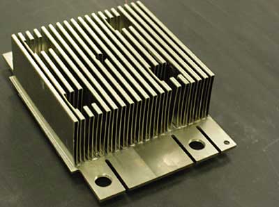
Alternatively, the fins can be fabricated in a separate process in the form of metal strip and then bonded to a metal base by a variety of methods involving metallurgical bonding or thermally conductive epoxy adhesives. Figure 3 shows a heat sink with folded fins and a base containing a vapor chamber for heat spreading enhancement.
Figure 3. Heat sink with folded fins and base containing vapor chamber (Thermacore).
- Introducing discontinuities in the fin surface to break up the boundary layer.This can be accomplished simply by crosscutting an extruded aluminum heat sink to create a segmented fin or pin fin heat sink (Figure 4). In the case of bonded fins, it can simply be a matter of punching slots in the fins before attachment to the heat sink base. More advanced methods such as casting or metal injection molding have been applied to create more streamlined shapes to enhance the heat transfer to the air while moderating the increase in pressure drop across the heat sink [14].
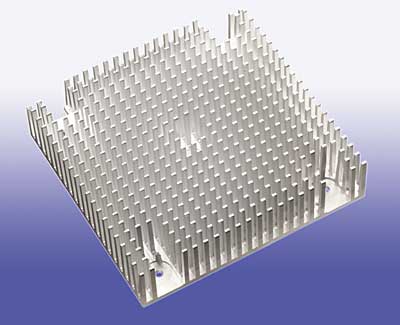 |
Figure 4. Pin fin heat sink – crosscut extrusion (Aavid).
This past decade has seen considerable ingenuity in producing cost-effective heat sinks with a level of thermal performance beyond what was believed to be possible. Nonetheless, in the highest power applications, such as for servers, water-cooling is being seriously considered as an alternative to air-cooling [15].
Fans
Developments in fan technology closely paralleled developments in heat sinks. Fans have been subject to the same cost sensitivity and form factor demands as heat sinks. For example, miniature fans are now being used in laptop computers. Since fans are active devices, noise and long-term reliability are further considerations [16].
The heat removal capability of a heat sink is directly proportional to the mass flow of air through its fin structure. A simple way of getting higher thermal performance from a heat sink is by pushing more air through it. However, in life, nothing is free, so using a fan at a higher pressure drop leads to greater power consumption in moving the air and greater noise. This is the inevitable struggle in fan usage [17].
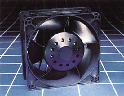 |
Figure 5. Axial fan (Comair Rotron).
The axial fan (Figure 5) remains the most often used solution since it works best at high flow rates and low pressure heads. However, as limits in the air cooling of high-power devices are reached, higher pressures are required. In these applications, radial fans (blowers) are finding greater applicability (Figure 6) [18, 19].
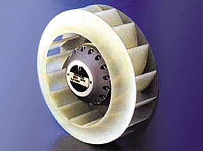 |
Figure 6. Radial fan (Papst-Motoren).
Mixed-flow fans represent an intermediate solution between axial and radial designs. In mixed-flow fans, air is drawn into an impeller axially and exhausted diagonally. As a result, the mixed-flow fan can generate a higher pressure for the same overall dimensions and speed than an axial fan. However, it cannot achieve the pressure values of a radial fan. It is finding application in large scale servers, which need the axial fan form factor but with a higher pressure drop to attain their cooling objectives.
Fan vendors are providing more intelligent speed control circuitry, which throttles the fan speed under reduced heat load conditions to save energy and reduce noise generation. Hence, the story of fans during this period has been more of an evolutionary process rather than one marked by the emergence of breakthrough technologies.
Heat Pipes
Adding liquid or two-phase cooling for thermal management has many attractive features from a thermal standpoint, such as reduced volume requirements and lower temperature differences. However, active thermal management with a coolant other than air usually increases the cost and complexity of a system. Transfer of thermal energy via heat pipes allows much of the benefits of two-phase liquid cooling while still being considered a passive device because the working fluid is contained within a sealed container. Heat pipes have become affordable for consideration as thermal management hardware in the past ten years, primarily as a result of widespread use in commercial electronics cooling. Figure 7 illustrates heat pipes used to transport heat from a source to an array of air-cooled fins, allowing the fins to be placed in a location easier to air-cool. Figure 8 shows a flexible heat pipe enabling the designer to move heat around other objects in the product. Heat sinks are now available with heat pipes embedded in the base to allow better utilization of fins that are some distance away from a centralized heat source.
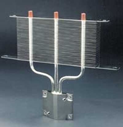 |
Figure 7. Heat pipe/radiator (Thermacore).
While the choice of working fluid, wicking structure, and housing material for a heat pipe can be complicated depending on the application [20], most of the cost reductions have occurred in heat pipes that operate in the electronics cooling temperature regime and use water, methanol, or acetone as the working fluid. When using water, a common concern is exposure to freezing temperatures. Properly designed, freezing of the working fluid does not do permanent damage and testing of copper water heat pipes have been shown to have adequate reliability for most electronics cooling applications [21]. In response to continually increasing heat loads and performance requirements, heat pipe research is continuing to provide additional thermal management hardware. Loop heat pipes (a configuration where the liquid and vapor do not move opposite each other but rather travel around in a loop) are capable of larger heat fluxes with less sensitivity to gravity. Loop heat pipes are still expensive but are moving towards configurations, and one hopes, costs that will give the thermal engineer another choice of thermal management hardware [22].
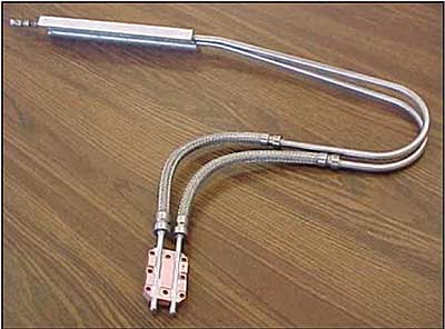 |
Figure 8. Flexible heat pipe (Swales Aerospace).
Software
While not a cooling solution per se, numerical simulation of electronics packaging for thermal predictions has become common across the electronics cooling industry in the past decade. Personal computer clock speed and graphical user interface improvements now allow complex conjugate heat transfer simulations on personal computers. Figure 9 illustrates an example of the complex geometry and fluid dynamics simulation routinely performed by thermal engineers today. The ability to predict the performance early in the design stage has reduced the design cycle time and reduced the number of prototypes required in product development.
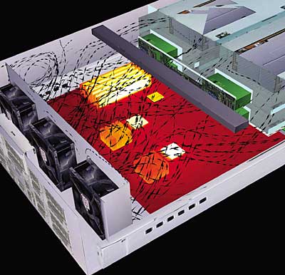 |
Figure 9. Thermal fluid modeling complexity (Flomerics Ltd).
Software improvements have occurred both at the macro (system) level and at the micro (individual transistor) levels. Detailed simulations of transistors and local semiconductor hot spots were mostly topics of interest for research ten years ago but are now common. Increases in die-level heat dissipation and the need to understand local temperatures at the die-level are responsible for this trend. While transistor-level temperature-prediction tools were routine for steady-state microwave devices in 1995, solution algorithm improvements and of course the ever-increasing computing power in the past ten years allow transient simulations to be completed quickly enough to allow concurrent thermal and electrical design [23].
Even with all of the faster computers and better software available today, including complete package level geometry into a system model is cumbersome at best and most likely impossible. The thermal behavior of packages can be included in a system model with the use of a package level compact thermal model. Standards for generating compact thermal models were in their infancy ten years ago but are now are broadly accepted [24]. Package vendors are now much more likely to supply enough detail to allow the thermal engineer to either construct his own compact thermal model or even supply the model themselves.
A discussion on software would not be complete without a word of caution regarding neglect of experimental confirmation. There is still a bias towards believing the pretty color image on a computer screen and even perhaps relying on the convergence monitors within the simulation software that the results are accurate. Understanding the thermal/fluid physics of the model in question is necessary for useful interpretation of results and even then, knowledgeable thermal engineers do not expect very accurate results [25].
Standards
A megatrend that was in process during the past decade was the end of the vertically-integrated electronics company as a viable business model. It was replaced with a very complicated supply chain involving companies from all over the world. Furthermore, increased competition to attract consumers who were looking for the latest and greatest in electronic gadgetry led to downward pressure on prices and to the need for reduced product development cycle times. In this highly diverse marketplace, standards of all sorts are critical to its smooth functioning. Otherwise, it is likely that companies will, in effect, speak different languages when it comes to the performance characterization of components and subsystems. This sort of inefficiency is at cross purposes to success in the marketplace.
In the area of IC package thermal characterization, the JEDEC (Joint Engineering Device Council of the Electronic Industries Alliance) JC15.1 Thermal Standards Committee became the premier standards body. The committee responded to the needs of the market for greater precision in measuring package thermal performance by providing a portfolio of standards related to the testing of IC packages [26]. The charter of the committee requires that these standards must be meaningful, consistent, and shall be proven to be scientifically sound. This mandate produced a rigorous process of validation of the requirements of the standards by thermal simulations and round-robin testing. The testing standards portfolio is divided into four categories: test method (i.e., instrumentation and procedure appropriate to the temperature-sensitive parameter being measured), test environment (e.g., natural convection, forced convection, etc.), component mounting (e.g., test board design), and device construction (e.g., thermal test chip) [24, 27].
Along with the more precise definition of test hardware, instrumentation, and test conditions, a number of test parameters were defined to supplement the θja test metric, which is essentially a figure of merit for ranking the thermal performance of competing packages, with newer ones (θjb, Ψjb, Ψjt), which can be used to calculate the chip temperature with respect to that of either the top of the package or the package attachment area on the board [28]. A recently published guideline provides a concise summary of the JEDEC test standard requirements [29].
The combined effects of proliferation of a large variety of package styles and the need for shortened product development cycle time has led to an increased importance of simulation, in thermal characterization, both at the package and system levels.
To achieve this end, the committee has expended considerable effort with the intent of generating standards and guidelines that apply to both detailed package thermal models (using finite element analysis, for example) and compact thermal models (CTMs). A CTM is essentially a thermal resistor representation of the thermal response of a package, subject to dissipated power levels and boundary conditions of temperature and heat flux (Figure 10). Refinements in the process for generation of CTMs were an outcome of the DELPHI Consortium in Europe [30]. Participation by members of this consortium on the JC15.1 Committee played an essential role in this effort. The process of extracting the CTMs can give them a high level of boundary condition independence. This allows the CTM to provide accurate predictions of chip temperature when imported into a wide variety of system-level models.
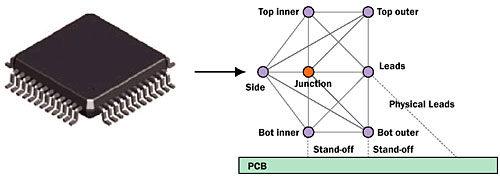 |
Figure 10. Quad leadframe package and the equivalent thermal compact model [31].
The JC15.1 Committee is currently going through a balloting process for these standards and guidelines. In deference to the large investment by industry in legacy data and test equipment based on existing JEDEC standards and inertia in the industry, the committee is striving to provide a migration path from a very simple 2-Resistor CTM based only on JEDEC test metrics to the more rigorous DELPHI approach.
Conclusions
Developments in thermal management methods and hardware made in the past ten years are currently allowing higher heat dissipations in today’s electronic packaging. This trend can be expected to continue and while many of the developments are evolutionary in nature, the need to minimize thermal resistances between the coolant and heat source provides a ripe field for innovation. The nearly inevitable adoption of liquid cooling in commercial packaging will demand the need for standards and affordable thermal management hardware.
References
- Guenin, B., “Packaging: Designing for Thermal Performance,” ElectronicsCooling, Vol. 3, No. 2, May 1997.
- Guenin, B., “The Many Flavors of BGA Packages,” ElectronicsCooling, Vol. 8, No. 1, February 2002.
- Mulgaonker, S., Chambers, B., and Mahalingam, M., “An Assessment of the Thermal Performance of the PBGA Family,” IEEE Trans. Comp., Packaging, Manuf. Technol. A, Vol. 18 Dec. 1995, pp. 739-748.
- Yovanovich, M., “Four Decades of Research on Thermal Contact, Gap, and Joint Resistance in Microelectronics,” IEEE CPT Trans., Vol. 28, 2005, pp. 182-206, 2005.
- Mahajan, et al.,”Thermal Interface Materials: A Brief Review of Design Characteristics and Materials,” ElectronicsCooling, Vol. 10, No. 1, February 2004.
- Blazej, D., “Thermal Interface Materials,” ElectronicsCooling, Vol 9, No. 4, November 2003.
- ASTM D 5470, Standard Test Methods for Thermal Transmission Properties of Thin Thermally Conductive Solid Electrical Insulation Materials, American Society for Testing and Materials, West Conshohocken, PA, HREF=”http://www.astm.org”>http://www.astm.org
- ASTM D 374, Test Methods for thickness of Solid Electrical Insulations Materials, West Conshohocken, PA, http://www.astm.org
- Lasance, C., “Problems with Thermal Interface Material Measurements: Suggestions for Improvement,” ElectronicsCooling, Vol. 9, No. 4, November 2003.
- Viswanath, R., Wakharkar, V., Watwe, A., Lebonheur, V., “Thermal Performance Challenges from Silicon to Systems,” Intel Technology Journal, Volume 4, Number 3, 2000.
- http://www.btechcorp.com
- Vogel, M., Xu, G., “Low Profile Heat Sink Cooling Technologies for Next Generation CPU Thermal Designs,” ElectronicsCooling, Vol. 11, No. 1, February, 2005, pp. 20 – 26.
- Soule, C., “Future Trends in Heat Sink Design,” ElectronicsCooling, Vol. 7, No. 1, February, 2001, pp. 18 – 27.
- Johnson, J. L., Tan, L-K., “Metal Injection Molding Of Heat Sinks,” ElectronicsCooling, Vol. 10, No. 4, November 2004.
- Schmidt, R., “Liquid Cooling is Back,” ElectronicsCooling, Vol. 11, No. 3, August 2005.
- Kim, S., Claassen, A., “How to Evaluate Fan Life,” ElectronicsCooling, Vol. 2, No. 2, May 1996.
- Wirtz, R.A., “Quick and Easy Fan/Sink Characterization,” ElectronicsCooling, Vol. 8, No. 3, August 2002.
- Angelis, W., “General Aspects on Fan Selection and Layout,” ElectronicsCooling, Vol. 7, No. 2, May 2001.
- Turner, M., “All You Need to Know about Fans,” ElectronicsCooling, Vol. 2, No. 2, May 1996.
- http://www.cheresources.com/htpipes.shtml
- Vukovic, M. and Watkins, J., “Reliability Characterization of Copper/Water Heat Pipe Below 0 °C,” Advances in Electronic Packaging, EEP-Vol. 26-2, InterPACK 99, ASME, June 1999, pp. 1979-1987.
- Maydanik, et. al, “Minature Loop Heat Pipes – A Promising Means of Cooling Electronics,” IEEE CPT Trans., Vol. 28, pp. 290-296, 2005.
- Wilson, J. and Raad, P., “A transient self-adaptive technique for modeling thermal problems with large variations in physical scales,” Intl. Jour. of Heat and Mass Transfer, Volume 47, Issues 17-18,, pp. 3707-3720, August 2004.
- Guenin, B. “Component thermal characterization,” Electronics Cooling, Vol. 7, No. 1, February, 2001.
- Lasance, C., ” CFD Simulations in Electronic Systems: A Lot of Pitfalls and a Few Remedies,” Electronics Cooling, Vol. 11, No. 2, February, 2005.
- JEDEC IC package thermal test standards are available for downloading at no cost at www.jedec.org. To access them, search for the character string, “JESD51.”
- Guenin, B. “Thermal Standards for the 21st Century,” Proceedings, SEMI-THERM XVIII Conference, March 2002, pp. 1 – 7.
- Joiner, B. “Use of Junction-to-Board Thermal Resistance in Predictive Engineering,” Electronics Cooling, Vol. 5, No. 1, January, 1999, pp. 14-17.
- JEDEC document JESD51-12, “Guidelines for Reporting and Using Electronic Package Thermal Information.” Available for download at www.jedec.oz
- Rosten, H., Lasance, C., and Parry, J., “The World of Thermal Characterization According to DELPHI – Part I: Background to DELPHI,” IEEE Trans. CHMT, Vol. 20, 1997, pp. 384-391.
- S. Shidore, “DELPHI Compact Thermal Model Guideline,” presentation to JEDEC JC 15.1 Committee, June, 2005.

