There are 819 kinds of Thermal Interface Material (TIM) – those greases, putties, pads and phase change compounds that go between hot electronic components and their heat sinks – and just as many ways to misuse them. This article covers all of them by stating: If a TIM disappoints, it is all your fault for making one or more of these silly mistakes.
Never Learning How to Make a Grilled Cheese Sandwich (GCS)
Before choosing your next TIM, make a dozen grilled cheese sandwiches. Achieving the perfect GCS and creating the ideal thermal joint between component and sink have many things in common. The bread must be heated evenly so that the cheese inside melts at exactly the same time that the surface toasts golden brown. Poor contact between the bread and the grilling surface yields a blackened, cold, yucky, chunky cheese sandwich. Here are three key elements to the perfect GCS (and heat sink joint):
Flatness – Use a flat-bottomed frying pan or, even better, a griddle. A bowl-shaped pan will make contact only with the outer edges of the bread. The edges will burn and the center will be raw. A domed pan will touch the bread only in the center, burning it there before the outer edges cook. Flatness and parallelism is likewise critical for getting a good thermal joint between a heat sink and component. Cupping, doming, or waviness in one or both surfaces means that they will touch each other in only a few tiny spots, instead of the broad area you imagine. Heat funneled through tiny areas means a large temperature rise across the gap.
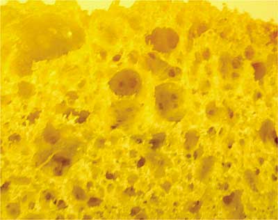
Butter the bread – On the outside! Why butter the surface that touches the pan? I used to think it was to keep the bread from sticking to the pan. But sticking only happens if the bread burns. The real reason should be obvious from Figure 1, a not very magnified picture of the surface texture of bread. The surface is full of bubbles that formed during baking. My careful analysis of this photo shows that only about 11.4% of the surface is solid bread material and the rest is air. Only 11.4% makes contact with the hot pan. The rest of the sandwich is insulated from the pan by pockets of dead air. Heat has trouble getting to the cheese before the 11.4% burns. Butter fills the holes in the surface, displacing the air with a semi-solid that conducts heat much better. The buttered sandwich cooks more evenly, with less chance of burning, because there is more solid surface area in contact with the frying pan.
 |
Figure 1. Micrograph of the grain structure and porosity of a commercial grade extruded aluminum heat sink base. OK, not really. It’s a slice of homemade white bread. But on a much, much smaller scale, the aluminum surface does look something like this. And so does the surface of the plastic case of the electronic component.
[Photo courtesy of TK Labs & Kitchen]
The butter is the TIM for the sandwich. It’s like the thermal grease on the base of a heat sink. Thermal grease isn’t meant to fill large gaps between the component and heat sink. It works by wetting the two surfaces, filling the microscopic pores and scratches, displacing air bubbles with material of higher conductivity. The grease layer should be as thin as possible. The same thing applies to phase change materials, today’s no-mess version of grease. Let the bread touch the pan wherever it can. But fill the pores with butter.
Pressure – After the butter starts to sizzle, smash the sandwich into the pan with the bottom side of a pancake turner. My tongue says it just tastes better flattened, but my brain tells me it’s because the pressure crushes a bunch of those surface air bubbles flat, increasing the surface area of bread in contact with the pan. It also gets the cheese closer to the heat, promoting quicker melting. The same thing is true for your heat sink/component joint. The joint thermal resistance always goes down with pressure, even with grease. It makes sense that if you deform the tiny bumps and pinnacles of the surfaces, you can get more solid-to-solid contact. Don’t forget the smashing! It’s especially important if your TIM is a spongy, gap-filling pad. They usually need a minimum of 10% compression to really conform to the nooks and crannies of the solid surfaces.
Obsession with Maximum k
Should you go with the alumina-filled, the silver-filled, or the diamond-filled epoxy between the component and the cold plate? The temptation is to pick the one with the highest value of thermal conductivity (k). That’s only natural, since you assume the
ΔTjoint = ( Q t ) / (k A)
where Q is the heat dissipation, t is the thickness of the epoxy layer, A is the area of the epoxy joint, and k is the thermal conductivity of the epoxy. The temperature rise is inversely proportional to k, so the material with the biggest value of k will give the lowest temperature rise. The diamond-filled stuff is pricey, but worth it when you’re fighting for every degree.
But conduction through the epoxy layer may be the smallest thermal resistance in the joint. There are two other thermal resistances that can’t be ignored, (even though you can’t evaluate them from the epoxy vendor’s data sheet): the contact resistance between the component and the epoxy, and the contact resistance between the cold plate and the epoxy.
The value of those two contact resistances depends on the material properties and surface finishes of both your component and your cold plate, and how they interact with the surface properties of the epoxy. If the epoxy really wets the surface before it hardens, then the contact resistance should be relatively low. But maybe the surface of your plastic-bodied component repels the epoxy. Have you ever tried to write on a polyethylene margarine tub with a ballpoint pen? The ink doesn’t stick – it stands up on the surface in little spheres that wipe right off.
If that is how the epoxy reacts to your component, the contact resistance will be relatively high. The temperature rise due to high contact resistance can swamp the temperature rise through the epoxy layer itself. If the epoxy doesn’t wet both surfaces, you’ve wasted your money on expensive diamond filler. It is more important to find a thermal interface material that is compatible with the surfaces you are trying to join. Focusing only on k is a big mistake. It is an easy mistake, because k is the only number in the data sheets. But that is why some vendors always tell you to evaluate the performance of the material in the actual application. It doesn’t matter how well a TIM connects two blocks of copper in the lab, unless your product is two blocks of copper stuck together with epoxy.
Testing TIMs on the cheap
I finally convinced my buddy Herbie to try out his TIM candidates on actual components with actual heat sinks. After several days of testing, he still hadn’t picked a winner. The thermal performance of the TIMs seemed to change from trial to trail. Pad “X” seemed bad at first, but then did much better in follow-up trials. I asked, “Did you test each sample with a separate component and heat sink?” Herbie explained that he could afford only one sample component and had to use it over and over, cleaning it between trials with whiteboard cleaner spray. Apparently Pad “X” did not wet the component surface well when it was fresh and clean, but after some of the other TIMs were applied and partially cleaned off, Pad “X” wet the component much better. Testing TIMs can be tricky. Contamination like dirt, human “Cleanliness is next to impossible.”
Magical thinking
Magical thinking is that very human brand of reasoning that leads us to forget both science and common sense and believe that certain substances have miraculous
I encountered magical thinking one day long ago in a design review. I presented some thermal test data for a processor chip that was running too hot. With no heat sink it had a junction temperature of 101°C. With a heat sink the junction temperature dropped to 90°C, still too hot. After adding a particularly effective TIM, the junction °C, which was great, because the goal was to stay below 85°C. Naturally, I recommended adding the sink and TIM.
The Project Manager smiled wisely. “Why add both?” he reasoned, “The heat sink is only good for a 10° drop, but the TIM is good for 20°. We only need a 20° improvement to pass. Let’s just use the TIM by itself.”
Thermal Interface Materials do not have the magical ability to absorb heat and make it disappear, or to lower temperatures all by themselves. They are not even good heat spreaders. Compared to aluminum (k = 160 W/m°C), even the best TIM (k = 9 W/m°C) should still be considered a pretty good thermal insulator. When used properly – that is, between flat surfaces, with good wetting, appropriate pressure, and tested in the real application – a TIM, at best, has the amazing ability to make a heat sink do what you thought it was supposed to do in the first place by itself.
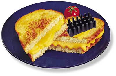
Now head for the kitchen and start practicing your GCS theory (Figure 2). Don’t worry if you make a few mistakes along the way. That’s how you learn. Grandpa likes his GCS slightly burned anyway.
 |
Figure 2. Never again think about sticking down a heat sink without first making a grilled cheese sandwich. [photo credit for grilled cheese sandwich on blue plate: Midwest Dairy Association]
Tony Kordyban is the author of the ASME Press books, Hot Air Rises and Heat Sinks: Everything You Know About Cooling Electronics Is Wrong and, its long-awaited sequel, More Hot Air. They tell stories similar to this one, including the thermal challenges in developing a telepathy-based telecom system. All of them are educational. Some are even true.


