Introduction
As part of contractual and design requirements, telecom equipment destined for certain networks in the North American market has to be tested to the Network Equipment Building System (NEBS) standard and comply with its requirements. NEBS is a standard from Telcordia, formerly known as Bell Communication Research (Bellcore). Technically speaking, NEBS is the Telcordia GR-63-CORE standard that governs hardware requirements related to environmental protection (temperature, vibration, etc.). It consists of various engineering requirements deemed essential to the reliability, availability and durability of the Public Switched Telephone Network (PSTN).
Testing and complying with NEBS require a concerted effort among various design organizations from the start of a design cycle. Since NEBS testing is usually conducted at the end of a design cycle, any nonconformance discovered at this stage could put the project in jeopardy. Of the various NEBS requirements, its thermal specifications are among the most stringent. This article will address some of the issues that are essential to thermal design and NEBS testing.
What is NEBS?
NEBS is a set of technical requirements and objectives that were originally developed by AT&T’s Bell Labs under the title of Technical Publications with the purpose of making network switches robust and reliable. After the 1984 divestiture of AT&T, NEBS ownership passed on to Bellcore (currently Telcordia), the research arm of Regional Bell Operating Companies (RBOC), for maintenance and upgrades. Since then Telcordia has renamed the publications Generic Requirements (GR) and published many new ones.
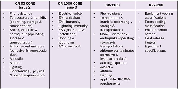
The NEBS requirements and test methods are specified in the Telcordia GR-63-CORE, GR-1089-CORE, GR-3109 and GR-3208 documents [1]. Table 1 lists the general topics of each document. Compliance to NEBS is demonstrated by testing products in a Nationally Recognized Testing Laboratory (NRTL) sanctioned by RBOCs or in the manufacturer’s test facility, supervised and witnessed by an NRTL. Depending on the application and the customer, compliance can be demonstrated on a tiered system defined in the Telcordia SR-3580 document as NEBS levels 1, 2 and 3, where level 3 is for Central Office (CO) grade equipment. NEBS level 1 is mandated by the Federal Communication Commission (FCC) for co-location of Competitive Local Exchange Carrier (CLEC) equipment in the Incumbent Local Exchange Carrier (ILEC) spaces.
Table 1. NEBS Requirements Topics
Other standards bodies, such as the European Telecommunication Standards Institute (ETSI) and American National Standards Institute (ANSI), have NEBS-like standards. Compliance to ETSI is a requirement for the majority of the EU countries. ANSI’s requirements do not cover all the subjects that NEBS does and are still in progress. Some ANSI standards, such as fire testing, have gained wide acceptance in the industry and NEBS refers to them. A few companies also have developed their own standards, such as Verizon’s NEBS, SBC’s TP-76200 and AT&T NEBS. These are usually a collection of references to the NEBS with additional company specific requirements.
Why NEBS?
The answer lies in the network reliability and longevity requirements. The PSTN was designed and is being operated by phone companies, which are considered utilities and are regulated by the FCC. The FCC requires certain network reliability and, at the same time, regulates the profit margins of the RBOCs and the phone rates. To keep the phone rate low, RBOCS are required to write off their capital expenditure in 20 to 25 years. This in turn compels RBOCs to hold onto most of their network equipment for a long duration and to update them only when the business requires it.
Thus, to fulfill FCC requirements and to protect their investments, RBOCs have been enforcing NEBS as a mean of increasing the reliability and quality of products in the network. An indicator of the achieved reliability is the downtime of telecom switches, which is measured in minutes per year. In comparison, most information technology or enterprise equipment has regularly scheduled maintenance and downtimes. Many of these telecom switches have been in the field for more than 20 years, still operating reliably and demonstrating the effectiveness of NEBS.
To verify NEBS compliance of a new product, RBOCs go through an approval process before deploying the product in their network. This is done by requiring the Telecommunications Carrier Group (TCG) NEBS Checklist [2] to be completed for each product and to be backed by test reports. This checklist was created by a consortium of telecom operators (Bell South, Qwest, SBC and Verizon) in 2004 to examine various aspects of NEBS compliance and to obtain information regarding power requirements, power dissipations and physical dimensions.
Telecom Equipment Environment and Structure
An understanding of the buildings and environments used for the network can further explain the reason behind some of the NEBS requirements. The structures used for housing network equipment are categorized based on their environmental and physical protections, which range from no control at all for outdoor equipment to full control in data centers. Some of the more common environments in the telecom market are as follows:
- Central Offices (CO) are usually very large buildings where phone companies house many PSTN components, such as class 4 and 5 telephone switches and transport equipment. The CO environments are air-conditioned and usually kept within a temperature range of 23 to 27�C. However, accounting for the possibility of air-conditioning and other failures, NEBS allows temperature fluctuations over the range, -5 to 49�C for short periods of time. The air-conditioned air is usually provided by dropped ceiling vents with a cooling capacity of about 500-1000 W/m2. Equipment is usually laid out along long narrow aisles, so temperature variations of up to 5�C are common. Recently some companies are experimenting with other cooling methods, such as raised floor plenum cooling, to increase the overall efficiency. The equipment in the COs is powered by -48 VDC, and in case of a power failure there is battery back up power for up to 8 hours of operation. COs are exempt from national fire codes and have no sprinklers.
- Mobile Switching Centers (MSC) are set up much like COs, but they are used for wireless networks equipment, which are not part of the PSTN, and therefore not regulated by the FCC. Nevertheless, many of the wireless operators require NEBS grade equipment for added reliability.
- Data Centers are generally used to house enterprise equipment, such as computers, servers and routers that were not the basic components of the PSTN. However, with the advent of the new telecom networks based on IP telephony and IP Multimedia Systems (IMS), data centers will be hosting progressively more telecom related equipment. Data center temperatures are kept within a range of 18 to 22�C. Temperatures as high as 35�C are allowed for short durations. Cooling is usually provided through the raised floor panels with capacities of up to 2000 W/m2. Currently there is no national standard similar to NEBS for data centers. However, Telcordia is planning to publish one and ASHRAE has also set up a committee to provide thermal guidelines for data centers [3]. Some RBOCs have announced their own requirements, similar to NEBS level 1. Except for electrical power at 110 or 220 VAC, any equipment designed to NEBS should be suitable for a data center application.
- Outdoor Environment applies to equipment housed in outdoor cabinets, huts, vaults or any environment without much control. The operating temperatures for this environment are in the range of -40 to 85�C. The outdoor cabinets are usually sealed. Cooling is done via heat exchangers and required heating is provided by the heat generated by the equipment. The use of military grade components is a common practice for this environment. When provided, the back up batteries are in separate compartment from the electronics and are usually equipped with heating units.
Designing for NEBS Thermal Specifications
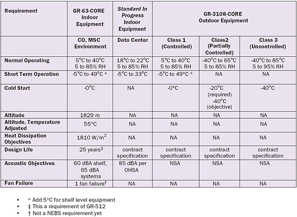
Thermal design and analysis for NEBS-grade products are, for the most part, the same as other electronic products. However, the operational thermal requirements of the NEBS (Table 2) make the design more challenging. The high operating temperature requirements combined with any acoustic objectives create limitations that do not exist for enterprise or computer industry products. To successfully design for NEBS, thermal analysis should be conducted early in the design cycle. This requires a good understanding of the power dissipations and the thermal limits of the components at the beginning of the design process.
Table 2. Operational Thermal Related Requirements
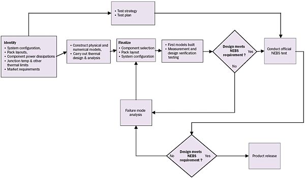
A computational 3D model of the airflow and temperatures may be helpful to the placement of the components on the printed wiring board (PWB) as well as overall system design and fan selections. Physical models should also be constructed early in the design process to allow adequate time to verify the validity of numerical analysis and optimize them for what-if scenarios. Figure 1 presents a simple but proven NEBS thermal design and testing process. To achieve a product life of 25 years, many component junction temperatures should be kept below 65 to 75°C, depending on the type of the components. For outdoor equipment, the designer should take into consideration the effect of fatigue induced by daily temperature fluctuations.
Figure 1. NEBS thermal design process.
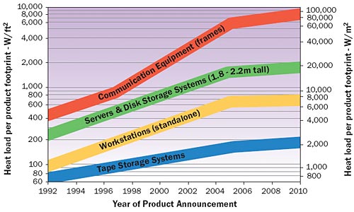
The other NEBS design challenge is to manage ever-increasing power densities. NEBS has set objectives on the limits of power dissipations. But, as shown in Figure 2, the power dissipation of telecom equipment has been increasing [4]. High power densities create a thermal design challenge [5] for equipment designers as well as a space cooling challenge for the RBOCs.
Figure 2. Power dissipation trend. (The Uptime Institute, Version 1.0, © 2000)
As noted earlier, the air conditioning systems for telecom environments are designed for a certain cooling capacity. Once that capacity is surpassed, adjustments are needed. Adjustments come in various forms; e.g., providing additional air conditioning capacity, depopulating cabinets and racks or dispersing the equipment. These solutions are neither attractive nor cost-effective and have their own limits. For instance, there are practical limits to the cooling capacity that can be provided by air-conditioners. This limit is reached at around 2000 to 3000 W/m2. So system designers need to limit power dissipation and power density when possible.
However, if current power trends do not change, it is likely that liquid cooling will be necessary in an increasing number of applications. Liquid cooling is coming back to data centers [6], but it would be prohibitively difficult to implement it in the existing COs due to water restrictions, equipment density and legacy infrastructure issues. This may push more telecom equipment into data centers or require RBOCS to look into the design of future COs where liquid cooling is an option.
NEBS Testing
NEBS testing is the last step in the design cycle. This is where the hardware and software have to be ready and integrated for the first time in a fully configured system. Since initial integrations are always a challenging process, enough time should be allocated for this step. A comprehensive test strategy and test plan should always be the first step in any NEBS testing. The test strategy should decide on matters such as tests to be carried out, number of EUTs (equipment under test), test location and other relevant information that affect the planning and budget. The test plan should contain the description of the EUT, set ups, logistics and pass and fail criteria among other necessary information. TCG provides a test plan and test report template in the required format for some RBOCS [2].
Tests must always be sequenced to address equipment availability, marketing needs and the designer’s priorities. For example, if there is only a single system available, then the fire test is the last. However, if NEBS level 1 is required initially for marketing reasons (some RBOCs require NEBS level 1 for lab deployment), the fire test would have to be moved up in the schedule. A full set of NEBS testing with a single system can take anywhere from three to six months. To reduce the test period it is always recommended to allocate multiple systems for NEBS testing. This will get the product to the market faster, reduce the wear and tear on the EUT and increase the probability of success.
Thermal and humidity tests are the longest NEBS tests and in total take about a month to complete. Even though not required, it is always a good practice to monitor internal system temperatures and, when dealing with marginal systems, to make sure the chamber fans are not interfering with the system fans in a negative way. Except for fire and airborne contaminates tests, NEBS testing should not be destructive. However, systems coming out of NEBS testing are not suitable for future testing. Reuse of the previously tested components increases the chance of failure and erroneous results.
Summary and Conclusion
Designing and testing for NEBS is a necessary step for manufacturers to market telecom products in North America. Obtaining NEBS compliance requires a concerted effort involving various engineering disciplines and is, by no means, an inexpensive proposition. It could easily become a large percentage of any new product development budgets. To insure a successful outcome, development organizations should have a clear focus on NEBS requirements and equip their staff with the proper and necessary tools for the task.
References
- www.telcordia.com
- www.verizonnebs.com
- Schmidt, Roger and Beaty, Don, “ASHRAE Committee Formed to Establish Thermal Guidelines for Datacom Facilities,” ElectronicsCooling, Vol. 11, No. 1, Feb. 2005, pp 28 -34.
- http://www.upsite.com/TUIpages/whitepapers/tuiheat1.0.html
- De Lorenzo, David D., Opdahl, Joseph B., “Server Design Challenges for the High Heat-Load Internet Data Center,” ElectronicsCooling, Vol. 11, No. 1, Feb. 2005, pp 12 – 18.
- Schmidt, Roger, “Liquid Cooling Is Back,” ElectronicsCooling, Vol. 11, No. 3, Aug. 2005, pp 34 – 38.


