Introduction
Control of component temperatures and temperature gradients is essential for the successful operation and reliability of electronics products [1]. However, conventional cooling methods, such as natural convection or fan-induced air-cooling, cannot cope with the increasing demand for electronics cooling. Therefore, more sophisticated cooling techniques are required. Forced convection microchannel liquid cooling has proven to be highly efficient, though a critical issue in applying microchannels for electronics cooling is the substantial pressure drop encountered over the heat exchanger.
This article investigates the combination of microchannel cooling with electrowetting actuation, based on the available expertise with electrowetting phenomena at Philips Research [2]. Electrowetting is a well-known technique to manipulate fluids on a millimeter or micrometer scale [3-5]. As such, it is already used in miniaturized chemical and biological reactors [3, 5]. This principle was recently investigated for its use in electronics cooling applications [6, 7]. In that investigation, the electrowetting action was controlled by numerous electrodes that were sequentially activated.
For the purpose of this article, the use of electrowetting by periodically filling and emptying microchannels for electronics cooling is discussed (see also [8]). In order to evaluate the cooling capacity of the proposed technology, the electrowetting phenomenon for pure water and water-glycerol-salt mixtures in microchannels is explored first. Subsequently, this experimental evidence is used to assess the heat transfer in electrowetted microchannels.
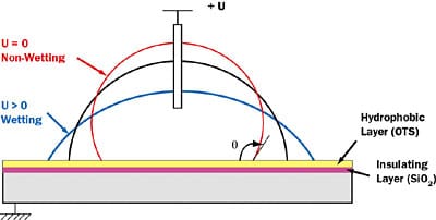 |
Figure 1. Principle of electrowetting: a voltage is applied between an electrode immersed in a conducting drop and the substrate. A dielectric layer insulates the drop from the substrate.
Electrowetting
The shape of a liquid droplet on a solid substrate is characterized by the contact angle θ between the liquid and the solid substrate (Figure 1). If the angle is less than 90° the liquid is said to wet the solid. If it is greater than 90° it is said to be non-wetting. Electrowetting is the phenomenon whereby an electric field can modify the wetting behavior of a droplet in contact with an insulated electrode. The shape of a droplet on an insulated substrate can be altered by applying a voltage difference U between substrate and liquid. The principle of electrowetting is illustrated in Figure 1. On a flat substrate, this effect is governed by Lippmann’s equation:
 |
where UL=(2DγLV/ε0 εr)1/2 is a characteristic of the system, with D the silicon oxide layer thickness, ε0 the dielectric permittivity of vacuum, εr the dielectric constant and γLV the liquid-vapor surface tension. It is this change in contact angle that can be used to move liquid over solid walls.
The liquid used in the experiments was either purified water or a mixture of glycerol (74.8% in weight), water (18.78%) and salt (6.5%). In the latter, glycerol was used to reduce evaporation and salt (NaCl) to increase the conductivity of the liquid. The experiments well satisfy Lippmann’s equation (1) up to 50V, resulting in a quadratic behavior. Furthermore, from the experiments it can be concluded that the salt-water-glycerol mixture provided the best wetting performance and therefore is used in the subsequent experiments.
Electrowetting on Microchannels
A drop deposited on open microchannels with a rectangular cross-section has multiple equilibrium states. There are typically two prominent states in which the drop can reside on the channels. Depending on channel geometry and liquid properties, the drop either sits on top of the channels or it wets the channels.
For the experiments, microchannels of 100 x 100 �m cross-section were produced using anisotropic ion etching. At the end of the etching process the insulating silicon oxide layer was thermally grown to a thickness D of 1 �m, and a hydrophobic OctadecylTrichloroSilane (OTS) monolayer was deposited on top of the oxide layer. A schematic of the structure of the micro channels is shown in Figure 2a.
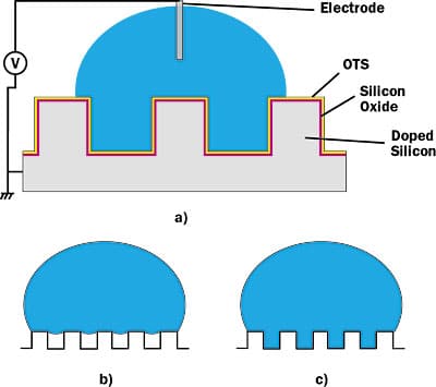 |
Figure 2. (a) Schematic of the square channels, w = d = 100 �m, light grey: Si substrate, dark grey: SiO2-layer, on top: OTS monolayer (not to scale). Possible droplet shapes on microchannel structure; (b) the droplet sits on the microchannels; (c) the liquid wets the microchannels.A 5 �l droplet deposited on the channels will not wet the microchannels. It will sit on top of the channels (Figure 2b). However, by applying a voltage, the liquid tends to wet the surface and the liquid will penetrate in the channels. If the voltage is increased even more, the liquid will spread by filling the microchannels. The filling length of the liquid in the microchannel is finite and determined by the applied voltage on one hand and by the frequency of the voltage source on the other.
The transition of a 5 �l droplet of the water-salt-glycerol mixture on the microchannels was monitored by the contact angle in Figure 3. Transition point ‘1’ indicates the start of the transition. At point ‘2’ the liquid wets all channels. From that point on, the filling of the microchannels grows with increased voltage. The filling and emptying of the channels in the presented experiments was established with a filling frequency of 0.1 Hz. A filling length of 1750 �m was realized for an actuation voltage of 53.6V.
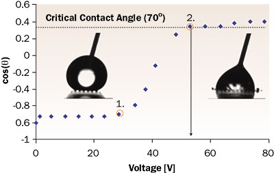 |
Figure 3. Contact angle measurements for the experimental set-up in use for a water-glycerol-salt mixture on a microchannel structure as a function of the applied voltage.
Heat Transfer Calculations
To assess the enhancement in liquid cooling that can be achieved by electrowetting, cooling capabilities of a system with electrowetted microchannels were compared to those of a system without microchannels. The reference system is a silicon block with dimensions lb x wb x db as presented in Figure 4. At the left surface, liquid flowing through an adjacent channel extracts the heat from the system. In general, most of the heat is dissipated at the bottom side of the chip.
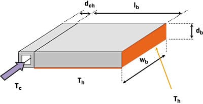 |
Figure 4. Schematic of the reference cooling system.Here we consider a worst-case cooling scenario where the heat dissipation is concentrated at the right side of the block. For this worst-case situation, the heat dissipation is assumed to be concentrated at the right side of the block. Therefore, the right surface and the bottom surface of the block are assumed to be heated up to a maximum allowed temperature Th.
In first approximation, the heat that can be extracted by the reference system is given by
 |
For typical dimensions in electronics cooling (e.g., dch ≈ 1 mm, lb = wb ≈ 10 mm and db ≈ 1 mm), the maximum heat transfer that can be extracted is limited both by the heat transfer coefficient in the channel and by the heat conduction through the Si-block. For this numerical example, the configuration would be capable to extract 0.9 W for a temperature difference of 50°C.
The cooling capabilities of the system can be increased by the addition of microchannels in the silicon block. The heat transfer to one microchannel will not increase by decreasing the microchannel dimensions, though the heat transfer coefficient will. However, decreasing microchannel dimensions would allow increasing the number of channels in the sample.
Keeping the same amount of water-cooled area, we would be able to increase the cooling inversed proportional to dch2. The drawback is that the pressure drop will drastically increase. In the electrowetted system, microchannels, connected to the main channel, are fabricated in the silicon block. In these microchannels a pulsating flow will be generated without the drawback of a high pressure drop.
A fraction v of the cross section of the silicon is replaced by microchannels. The total heat extracted by the system consists of a convective part by the pulsating liquid and a conductive part through the silicon block. The heat extracted by the liquid filling one channel during one filling period can be analytically calculated using the time-dependent filling function of the liquid in the channel (see [8] for details on the calculations).
The filling length L of the liquid in the microchannels can be described by the following equation:
where K is a parameter depending on the wetting properties of the liquid, the geometry of the channels and the applied voltage. From experimental data, we can conclude for the case at 0.1 Hz, filling frequencies and an actuation voltage of 53.6 V, K = 0.0015.
For a certain microchannel fraction v the conductive heat transfer through the silicon can be added to calculate the total heat extracted by the system. The effect of the microchannel fraction is linear between the reference case of convection of the main channel only and the hypothetic value for v = 1. In practice the value of v is limited to 0.5. The dependence of the heat transfer with the filling period and the fraction v is shown in Figure 5.
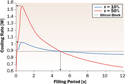 |
Figure 5. Comparison of the cooling rate of the silicon block and the structure with the channels as function of the filling period and for different values of the micrchannel fraction.From this figure it is clear that the different curves do intersect at a critical filling period. For shorter filling periods, the heat transfer will be improved by inserting microchannels. For higher filling periods, electrowetting deteriorates the cooling. For the example under consideration, this critical filling period amounts to 4.4s. A maximal cooling rate is achieved for an optimal filling frequency. For v = 0.5 the rate is nearly twice as high as for conduction cooling only. For the 100 �m square microchannels, this optimal frequency is 4 Hz. This is still a feasible frequency that can be achieved in the system using the electrowetting actuation.
It should be noted that in the previous computations convection resistances were in all cases most dominant. Therefore, top cooling of the chip with vertical microchannels will lead to similar conclusions. Both cooling rates for the silicon block as well as the actuated microchannel system will then be scaled with a factor of 10, given the increase in heat exchange area.
Conclusions
A new cooling technique was studied to enhance the heat transfer by means of electrowetting of microchannels in which the fluid oscillates. The main advantage is that no external pump is required. Typical filling length values of 1750 �m in 100 �m square channels were established with a glycol-salt-water mixture at an actuation voltage of 53 V a frequency of 0.1 Hz. Furthermore, a theoretical study of the heat transfer revealed that this new cooling method will induce enhanced heat transfer above a critical frequency. This frequency is about 0.25 Hz for the 100 �m square microchannels, and the improvement is about a factor of 2. It is expected that significantly better results can be achieved by further optimizing the channel layout and by using other fluids, such as liquid metals.
Acknowledgments
The research work of Herman Oprins is financed by a scholarship of the IWT, the Institute for the Promotion of Innovation by Science and Technology in Flanders, Belgium. Part of the work was performed by G. van der Veken for his Masters degree under supervision of C. Nicole, L. van der Tempel and C. Lasance of Philips Research, the Netherlands.
References
- Lasance, C., “Thermally Driven Reliability Issues in Microelectronic Systems: Status-Quo and Challenges,” Microelectronics Reliability, Vol.43, 2003, pp.1969-1975.
- Prins, M., Welters, W., Weekamp, J., “Fluid Control in Multichannel Structures by Electrocapillary Pressure,” Science, Vol. 291, 2001, pp. 277-280.
- Pollack, M.G., et al, “Electrowetting-Based Actuation of Droplets for Integrated Microfluidics,” The Royal Society of Chemistry, Lab Chip, Vol. 2, 2002, pp. 96-101.
- Washizu, M., “Electrostatic Actuation of Liquid Droplets for Microreactor Applications,” Vol. 34(4), 1998, pp.732-737.
- Cho, S., Moon, H., Kim, C.-J., “Creating, Transporting, Cutting and Merging Liquid Droplets by Electro-Wetting-Based Actuation for Digital Microfluidic Circuits,” Journal of Microelectromechanical Systems, Vol 12(1), 2003, pp. 70-80.
- Pamula, V.K. and Chakrabarty, K., “Cooling of Integrated Circuits Using Droplet-Based Microfluidics,” Proceedings ACM Great Lakes Symposium on VLSI, 2003, pp. 84-87.
- Oprins, H., Vandevelde, B., Beyne, E., Borghs, G., and Baelmans M., “Selective Cooling of Microelectronics Using Electrostatc Actuated Liquid Droplets,” Proceedings THERMINIC, Sophia Antipolis, 2004, pp. 207-212.
- Oprins, H., Nicole, C., Baret, J.C., Van der Veken, G., Lasance, C., and Baelmans, M., “On-Chip Liquid Cooling with Integrated Pump Technology,” Proceedings 21st SEMITHERM, San Jose, CA, 2005, pp.347-353.


