Introduction
Heat from electronic devices is an integral part of information processing, not a nuisance that can someday be eliminated. This is a physical principle that is independent of the device of information processing. However, when viewed in the historical perspective, the severity of heat problems has not monotonically increased. It came to the fore some time ago, then, was relieved almost disruptively when a new basic switching device for computing was developed. To recount briefly, we experienced such relief when the transistor replaced the vacuum tube, and the CMOS switch replaced the bipolar junction transistor (BJT) switch.
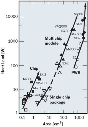 |
Figure 1. Rising heat dissipation from mainframes experienced in the period from the mid 1970s to the end of the 1980s [1]. Solid symbols = water cooled, open symbols = air cooled.Now, we are facing the challenge posed by growing heat dissipation from CMOS chips. We find ourselves in a situation similar to that of the 1980s when the heat from BJT chips soared [1, 2] as shown in Figure 1. Today the interest in high capacity cooling is renewed, and considerable investment is being made in the search for novel cooling schemes. If past experience indicates a cyclic demand for high capacity cooling, what will happen to the current need? Are there any technological developments that would possibly alleviate heat problems in the future? The answer is partly yes; work is in progress to curb the increase of power consumption by electronic equipment, although its impact on the future of high capacity cooling has yet to be proven. The benefits of power savings could be wide-ranging; the manager of the data center would be relieved from concern about a rising electricity bill, and the user of mobile equipment would enjoy longer battery life. Those power-saving technologies, some already in commercial products, provide the means to stay within the limits of traditional air cooling, countering the trend to achieve higher processing performance at the expense of increasing electric power. The actual development must balance the cost of cooling, the cost of electric power, and the demand for higher processing performance.
Looking back to the 1980s, we notice that the high-capacity cooling effort had its focus mainly on mainframes and supercomputers. Today, the inquiries about novel cooling schemes come from manufacturers of diverse products; not only high-end machines, but other equipment as well. Inquiries are motivated not only by the need to cope with rising heat dissipation, but also other needs, such as the reduction of acoustic noise and the integration of electromagnetic shielding and cooling functions. Another circumstantial change is apparent in the pace of design work. The time available for the equipment designer to work on the next generation product has been curtailed considerably; from a few years for designers of mainframes to a few months for those of consumer products. Diversity and acceleration characterize the present circumstance for electronics cooling.
This article is intended to address a wide range of electronic equipment. Consequently, it is necessary to use the simplest models of equipment and components. The limit of air cooling is an underlying theme. Understanding air-cooling limits is important to both groups of equipment designers; one exploring the switch to novel cooling schemes, and the other striving to stay within air-cooling limits. The limit of air cooling has been discussed repeatedly in the literature. The reader is referred to the latest update of this subject [3], which includes a list of previous publications and some specific design examples. In writing this article I leave most of what has already been discussed to the existing literature. Instead, I propose some means to quickly grasp the key determinants of air cooling limits, hoping that such an attempt will help time-constrained packaging designers.
Upper Bound of Heat Dissipation from a Fan-Cooled Box
For the purpose of discussion consider a box housing electronic devices. Cooling air is driven by a fan or several fans installed on the side(s) of the box. Besides the fan and the air inlet, the box needs ports on its surface for the electronic system to function and interact with the external world, such as power supply connects, communication connects, display panel and others. So, the size of the fan and the number of fans are constrained by the available area. Also, the dimensions of the box sets a constraint on the fan diameter.
Once a fan is chosen, the fan supplier’s catalogue may be consulted to find a maximum delivery in terms of the volumetric flow rate (Vmax [m3/min]). An upper bound to heat transfer (Qmax [W]) is computed from the enthalpy equation,
assuming what temperature is acceptable for the exhaust air (Te,max [°C]), that may be set about 10 K above the ambient (T ∞ [°C]). In equation (1), N is the number of fans, ρ is the density of air (1.16 kg/m3 at 300K), and c ρ is the specific heat at constant pressure of air (1000 J/kg K at 300K).
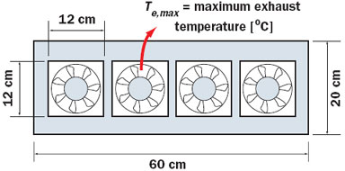 |
Figure 2. An illustration of commercially available fans that can be accommodated in an area of 20 x 60 cm.In the example of Figure 2 there is room for four fans. From a survey of fan manufacturers’ catalogues the values of Vmax for a fan of this size are found to cluster around 2 m3/min. In terms of the thermal resistance, the lower bound resistance is
In this example, 1.5 kW could be an upper bound heat dissipation for Te,max – T ∞ ≈10 K. This is obviously a very crude estimate, but helps to approximate the limit. The point is that the commercial availability of a fan is often a determinant of the air cooling limit. The limit here is set by the physics of enthalpy transport and the economy of procuring fans.
Heat Transfer from Finned Heat Sinks
Assume an idealized model of a finned heat sink that has uniform surface temperature and uniform surface heat transfer coefficient. The conductance of the finned heat sink (CHS [W/K]) can be written in a concise form using the heat exchange effectiveness (ε), the mass flow rate of air in the inter-fin passages ( [kg/s]), and the specific heat of air (cp [J/kg K]).
where Q is the heat flow [W], Tb is the heat sink base temperature [°C], and Tf1 is the air temperature at the inlet of the heat sink [°C]. The heat exchange effectiveness is defined as
where Tf2 is the air temperature at the exit of the heat sink [°C].
The conductance is actually a complex function of the fin dimensions, the air flow rate, and other parameters. However, ε at the optimum design points falls in a relatively narrow range; according to [4], ε = 0.63 when the pressure drop across the inter-fin passage is given, and 0.85 when the pumping power is given. In equation (3) the importance of the air flow rate is explicitly expressed.
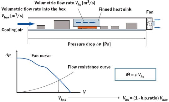 |
Figure 3. Airflow space in the fan-cooled box (upper illustration), and the steps to estimate mass flow rate () through the finned heat sink (lower illustration).Estimation of the flow rate in the inter-fin passages is a difficult task. The fan drives air through the box, and the volumetric flow rate is determined by finding a cross point of the fan curve with the flow resistance curve of the box, Figure 3. Estimation of the box flow resistance is not an easy task either; it involves a large number of design parameters, and its discussion requires an article of its own. Due to space limitations, only a rule of thumb is noted here; we choose the cross point at around two thirds of the maximum delivery point, where the acoustic noise is near minimum. Given the volumetric flow in the box (Vbox), we then try to estimate how much of it goes into the inter-fin passages of the heat sink (Vhs), and how much bypasses the heat sink (b.p.ratio x Vbox). Some methods to resolve the difficulty of bypass flow estimation have been proposed in the literature, for example, [5]. Presently, CFD codes are popular analysis tools for this purpose. However, it is still a difficult and time-consuming task for CFD analysts.
Because the analysis of heat transfer in electronic equipment in full detail is beyond the capacity of normally available computers, the CFD analyst has to divide his/her task into two parts, macro-scale analysis and localized analysis. In the first part, the geometric details of the components and their placements in the box are replaced by appropriate models; for the finned heat sink, a lumped resistance model is often used. In the second part, the analysis is focused on the heat sink, where the geometric details of the heat sink are restored and the solution of the macro-scale analysis serves to provide the boundary conditions for a volume to surround the heat sink.
The most serious impediment to this CFD task is the geometric complexity in the box that makes an accurate macro-scale analysis difficult. With increasing difficulty in achieving high accuracy in the macro-scale solution, the accuracy of the localized analysis also suffers. It is time-consuming to arrive at an appropriate box-level model that guarantees translation of sufficient accuracy to the heat sink level (component level). The geometric complexity is bound to increase with the progress of high-density packaging at the box level, costing many hours of work in setting up CFD models and evaluation of simulation results. Improvement in the productivity of CFD analysis is a widespread industrial need [6].
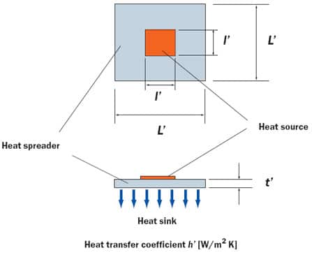 |
Figure 4. (a) Square heat spreader bonded to square heat source.
Heat Spreading
In recent years the development of new packaging materials has been accelerated. News about recently developed materials abounds at conferences and expositions, in publications and on the internet. Many of them are high thermal conductivity materials aimed at removing hot spots on the chip and the package [7]. One must keep in mind the fact that the effectiveness of a new material in heat spreading depends on the circumstance. In this section a way to gauge the heat spreader effectiveness is proposed. The vehicle of explanation is the simplest model; that is, a square spreader with a square heat source in the middle, Figure 4(a).
Table 1. Definition of Non-Dimensional Parameters Used in Equation (5)
The correlation proposed in [8] is rewritten using the non-dimensional parameters defined in Table 1
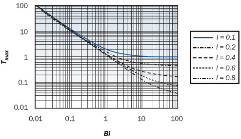
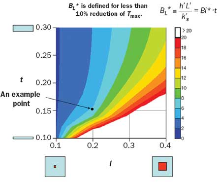
Equation (5) is plotted in Figure 4(b) for the relative thickness (t) of 0.2. As Bi (Biot number of Definition I, Table 1) increases, at some point, Tmax levels off, indicating that the heat transfer is constrained by heat conduction in the spreader. The point of near level-off, beyond which the increase of Bi does not produce less than, say, a 10% change in Tmax, will be referred to as the threshold Biot number (with an asterisk). Figure 5 shows the projection of the threshold Biot number, this time using Definition II of Table 1, onto the plane spanned by the relative heat source size, l, and the relative spreader thickness, t. A chart of this kind reveals the coupled effects of the surface heat transfer, the spreader thermal conductivity, and the geometric parameters on the condition of conduction-constrained heat transfer.
Figure 4. (b) Plot of equation (5); maximum heat spreader temperature (Tmax, non-dimensional) versus Biot number Bi, for the case of t = 0.2.
A quick study reveals that with air-cooled spreaders it is rare to encounter a conduction-constrained state. For example, consider a point of l = 0.2 and t = 0.15. At this point BL* = 6.5, meaning that where BL > 6.5, the heat transfer is constrained by heat conduction in the spreader. Where the dimensions of the spreader and the heat source are given, the value of BL* gives the threshold value of h’/ks‘. Assume a 2mm square heat source on a heat spreader having 10mm square area and 1.5mm thickness. The ratio h’/ks‘ corresponding to BL* = 6.5 is 650 [m-1]. Suppose that the thermal conductivity of an alumina ceramic substrate is around 30 W/m K. Then, the point of conduction-constrained heat transfer is reached when h’ is raised to 19,500 W/m2 K. Such a high value of h’ is beyond the range of air cooling. The use of aluminum or copper as a heat spreader pushes the threshold h’ further up, making the conduction-constrained state an even more remote possibility.
However, the argument developed here does not mean that the heat spreader is ineffective. It is effective in providing the extended surface area for convection heat transfer. The argument points to the fact that the bottleneck to the heat flow is in the resistance to convection heat transfer on the spreader surface. So, in most cases of air-cooled heat spreader, enhancement of convection heat transfer is more effective in lowering the heat source temperature than employing an expensive highly conductive material for the heat spreader. The only exception to this conclusion is the case with a very large finned heat sink attached to a small heat source; the corresponding point falls in the lower left corner of the chart of Figure 5. For such applications a large flat heat pipe serves as an effective heat spreader on which the fins are bonded.
Figure 5. Plot of threshold BL in the plane of relative heat source size (l) and relative heat spreader thickness (t).
Conclusions
In conclusion it may be noted that:
- The economical incentive to suppress system or box level power consumption is strong. The beneficiaries of power saving technologies are wide-ranging, from users of mobile equipment to data center managers. The benefit of power saving ultimately extends to the earth’s environment; note that the power consumption by electronic equipment amounts to a noticeable percentage of global power consumption.
- The effort to improve system performance within the bounds of power budget tends to concentrate computing tasks on those circuits in the path of vital data processing flow, thereby producing hot spots in the system. The easing of hot spots at the chip and package levels is becoming an issue of primary importance in the thermal design.
- Liquid cooling will be selected in high-end systems where the processing performance and the reliability are at the top of the priority list; it is already back in some [9]. However, vendors of liquid cooling devices will have to lower the device cost continuously to stay in the business, even in the realm of high-end systems. The cost pressure is immense as we go to lower-end products.
References
- Nakayama, W., “Japanese Supercomputers in Thermal Perspective,” High Performance Computing in Japan, ed. Mendez, R., Chapter 4, John Wiley & Sons Ltd., 1992, pp. 55-73.
- Oktay, S., Hanneman, R., and Bar-Cohen, A., “High Heat from a Small Package,” Mechanical Engineering, ASME, Vol. 108, No.3, 1986, pp. 36-42.
- Rodgers, P., Eveloy, V., and Pecht, M., “Limits of Air-Cooling: Status and Challenges,” 21st IEEE SEMI-THERM Symposium, 2005.
- Copeland, D. W., “Fundamental Performance Limits of Heatsinks,” ASME Journal of Electronic Packaging, Vol. 125, 2003, pp. 221-225.
- Simons, R. E. and Schmidt, R. R., “A Simple Method to Estimate Heat Sink Air Flow Bypass,” ElectronicsCooling, Vol. 3, No. 2, May 1997.
- Nakayama, W., “How to Beat Geometric Complexity (Editorial),” Heat Transfer Engineering, Vol. 27, No. 3, 2006, pp. 1-4.
- Zweben, C., “Ultrahigh-Thermal Conductivity Packaging Materials,” 21st IEEE SEMI-THERM Symposium, 2005.
- Lee, S., “Calculating Spreading Resistance in Heat Sinks,” ElectronicsCooling, Vol. 4, No. 1, 1998, pp. 30-33.
- Schmidt, R., “Liquid Cooling is Back”, ElectronicsCooling, Vol. 11, No. 3, August 2005, pp. 34-38.


