Introduction
Trends in power electronics systems and devices over the last decade have placed increasing demands on the efficiencies of the thermal management systems used for power Metal Oxide Semiconductor Field-Effect Transistor (MOSFET) and Insulated Gate Bipolar Transistor (IGBT) modules. The pressure to decrease the size of power electronics systems and, subsequently, the module, has resulted in a 50% footprint area reduction of some IGBT modules. This has resulted in higher power dissipation densities for the IGBT die as well as the module due to denser packing of the die. Increases in switching frequencies and voltage ratings of IGBTs also result in higher power dissipation at the die level. Even though a portion of the die power losses has been offset by advances in both MOSFET and IGBT chip design, the cooling capabilities of present modules limit the device performance.
Power modules used in Hybrid Electric Vehicles (HEV) provide an additional challenge in that the inlet temperature of the coolant can be over 100°C, requiring low temperature differentials (20 – 30°C) between the die and the coolant to keep the IGBT comfortably below the maximum operating temperature of 150°C, while simultaneously dissipating high heat fluxes. In other HEV designs, less efficient liquids, namely oil or transmission fluid, may be the only coolants available for cooling the power module.
Faced with the challenges of efficiently and economically cooling increasing power dissipation densities with low temperature differentials, power semiconductor module designers are turning to new heat sink technologies. In this article, several methods for reducing the thermal resistance of power modules are presented and compared in the context of a baseline 1200V isolated base IGBT power module design.
Comparison of Techniques for Reducing Thermal Resistance
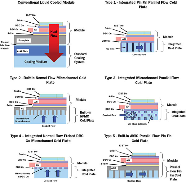
Most conventional power modules have been designed to be cooled by bolting the module to an external heatsink or cold plate cooled by forced air or circulated liquid. As shown in Figure 1, the critical layers in the thermal path of a conventional IGBT module are the IGBT die, the die attach solder, a metal-clad ceramic substrate (copper directly bonded on alumina or aluminum nitride), substrate attach solder, metal or composite baseplate, thermal interface material (TIM), and the external heatsink. The insulator provides electrical isolation between the die and the module baseplate. Aluminum nitride (AlN) is preferred over alumina (Al2O3) because of its higher thermal conductivity. With the many layers in the heat flow path, this configuration is not capable of adequately cooling devices with power dissipation densities beyond 250 – 300 W/cm².
Figure 1. Cross sections of the five heatsink concepts used in the comparison. A conventional liquid cooled module is shown for reference.
Recently, two complementary means of improving the effectiveness of power module cooling have emerged. One method focuses on reducing the thermal resistance by eliminating layers between the die and the cooling medium and also reducing the thickness and/or thermal resistance of the remaining layers. The second method has been aimed at increasing the efficiency of the cold plate by improving the heat transfer from the body of the heatsink to the coolant. Cross sections of five heatsink concepts that utilize one or both of these methods are shown in Figure 1.
In the remainder of this article, the performance of the five thermal management concepts shown in Figure 1 will be compared in a manner relevant to power module designers. These five concepts were selected because they are commercially available at the present or deemed to be commercially viable in the near future. The comparison will be made for a 1200V IGBT module design.
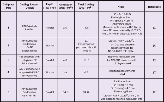
Table 1. Details of Five Heatsink Concepts Used in Comparison
Details of the five concepts are listed in Table 1. Two of the five heatsink types (Type 3 and Type 4) were fabricated with silicon die bonded to AlN substrates 0.635 mm thick, with 0.305 mm thick direct-bonded copper (DBC) layers commonly used in 1200V IGBT modules, so the published data was used as is. The other three types of heatsinks required adjustments to the reported data to obtain the overall junction to liquid thermal resistivity of the baseline IGBT module design. For example, if the thermal performance results reported in the literature included only the cold plate, the calculated thermal resistivity of the IGBT die, DBC AlN, and appropriate solder layers were added to determine the overall thermal resistivity from junction to inlet water. A simple one-dimensional heat flow calculation without spreading was used to calculate the thermal resistance:
Thermal Resistance= Layer Thickness
Thermal Conductivity x Area
An area of 1 cm² was used to obtain the thermal resistivity to facilitate comparison of the five concepts. It should be noted at this point that the values of thermal resistivity obtained using this simple model tend to be lower than actual measured values, which will likely show the performance of Types 1, 2 and 5 as somewhat better than can actually be obtained.
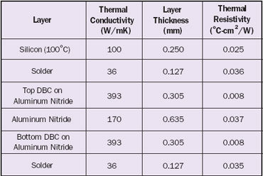
The Type 1 and Type 5 concepts are “pin fin” designs, which utilize turbulent liquid flow around staggered rows of pins to enhance heat transfer to the liquid. Both concepts utilize coolant flow parallel to the heat generation surface. The Type 1 pin fin design consists of copper pins brazed directly to the bottom DBC layer of the AlN insulator. The pin fin AlN substrate is brazed to a copper baseplate, which is then bolted to a block that serves as the water inlet/outlet manifolds and flow channel [1]. The flow channel was designed to minimize water flow outside of the pin array. This cold plate was fabricated using 1.0 mm thick AlN, so the measured junction to water thermal resistivity was reduced by a calculated factor of 0.0215°C-cm²/W (the difference between the AlN thickness of 1.0 and 0.635 mm) to permit direct comparison with the other concepts. The Type 5 design is a stand-alone Aluminum Silicon Carbide (AlSiC) cold plate with molded pins of AlSiC [2]. For comparison to the other designs, a calculated thermal resistivity of 0.149°C-cm²/W for was added to the reported values to simulate the layers from the die to the top surface of the coldplate. The layer thicknesses and values of thermal conductivity used are listed in Table 2.
Table 2. Layer Properties Used to Calculate Thermal Resistivities in Heatsink Comparison.
 |
The Type 3 concept utilizes microchannels with coolant flow parallel to the heat removal surface [3,4]. This design employs the process for direct bonding of copper to AlN to laminate up to 11 thin copper layers with etched holes between two AlN substrates. The holes in each layer are offset to provide a serpentine path for the coolant, maximizing surface area and ensuring turbulent flow. The IGBT chip is soldered to the top AlN substrate, permitting this design to be integrated directly in the module package.
The Type 2 configuration is a commercially available, normal flow, microchannel heatsink (NFMCH) and is a stand-alone copper cold plate with multiple, densely packed micro-streams of coolant impinging on the heat acquistion surface at right angles [5]. As in the case of the Type 5 cold plate, a thermal resistivity of 0.149°C-cm²/W was added to the reported values to simulate the layers from the die to the top surface of the coldplate.
The Type 4 concept is a NFMCH heatsink that utilizes microchannels machined in the bottom DBC copper layer of the AlN substrate coupled with a manifold that delivers coolant flow normal to the DBC layer [6]. Since the reported results were from an actual 1200V IGBT module [7], no adjustments were necessary. In this concept, as is the case with the Type 1 and Type 3 designs, the coolant is brought as close to the die as practical.
The power module designer must balance several tradeoffs when selecting a thermal management method, namely thermal resistivity, required flow rate, pressure drop, type of coolant, size, weight, reliability, and cost. The first three performance parameters will be compared in this article. Comparing different heatsinks on the basis of absolute flow rates can be misleading since they are invariably different sizes and shapes, and have varying heat generation and cooling surface areas. These differences can be seen in Table 1 for the five types considered here.
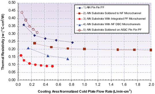
A more valid comparison is to normalize the absolute flow rate of each heatsink to the total cooling surface area. The area normalized flow rate is especially relevant for normal flow heatsinks since the inlet water streams to the cooling surface are basically in parallel. The thermal resistivity (junction – water) for the 1200V IGBT baseline module designed with each heatsink concept is plotted as a function of water flow rate per total cooling area in Figure 2. Since the same unit volume of water is used to cool the entire heat removal surface area, the parallel flow heatsinks require lower flow rates. However, the increase in coolant temperature along the length of the water flow path can lead to temperature non-uniformities within the power module.
Figure 2. Comparison of thermal resistivities from junction to water of 1200V IGBT power modules fabricated with the five types of heatsink designs vs. water flow rate normalized to the total heatsink surface cooling area.Finally, the thermal resistivity as a function of pressure drop of each heat sink type is plotted in Figure 3. Due to their short flow passages compared to parallel flow designs, normal flow heatsinks exhibit lower pressure drops. The pressure drop in parallel flow heatsinks is partially dependent on the channel length to width aspect ratio. One means of decreasing the pressure drop and improving the temperature uniformity of parallel flow designs is to decrease the aspect ratio. The lower the aspect ratio becomes, the more the parallel flow design resembles the normal flow design with the subsequent increase in required flow rates.
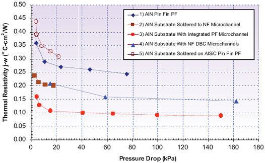 |
Figure 3. Comparison of thermal resistivities from junction to water of 1200V IGBT power modules fabricated with the five types of heatsink designs vs. water pressure drop.
Conclusions
Several methods for improving the thermal performance of high-power semiconductor modules have been presented and compared. The baseline design of a 1200V IGBT module with an electrically isolated base was used as a basis for comparison. Removing layers in the heat flow path led to the lowest thermal resistivities. As would be expected, the normal flow heatsinks had lower pressure drops than the parallel flow concepts due to the short flow passages.
References
- Litvinov, A., Powerex, Inc. Private Communication, July 2006.
- Moores, K., Joshi, Y., and Schiroky, G., “Thermal Characterization of a Liquid Cooled AlSiC Baseplate with Integrated Pin Fins,” IEEE Transactions on Components and Packaging Technologies, Vol. 24, June 2001, pp. 213 – 219.
- Credle, K., Exel, K., Meyer, A., and Shulz-Harder, J., “New Generation of DBC Substrates for High Efficient Cooling of Power Devices,” Proceedings of International Conference and Exhibition on Power Conversion and Intelligent Motion, PCIM’98, Nurenberg, Germany, 26-28 May 1998, Curamik/Electrovac Website, www.electrovac.com (publications page).
- Schulz-Harder, J., “Efficient Cooling of Power Electronics,” Proceedings of the Power Conversion and Intelligent Motion Conference – China (PCIM – China), Shanghai, China, 2006.
- Valenzuela, J., Jasinski, T., and Sheikh, Z., “Liquid Cooling for High Power Electronics Technology,” Power Electronics Technology, February 2005, pp. 50 – 56.
- Solovitz, S., Stevanovic, L., and Beaupre, R., “Microchannel Thermal Management of High Power Devices,” Proceedings of the Applied Power Electronics Conference (APEC),Dallas, Texas, 2006.
- Stevanovic, L., Solovitz, S., and Beaupre, R., “Advanced Power Module with Integrated Microchannel Cooling,” Proceedings of the Electric Machines Technology Symposium, Philadelphia, Pennsylvania, 2006.
- Mikros Datasheet, Normal Flow Cold Plate NCP-A-10-20, Mikros Website, www.mikrostechnologies.com.

