In recent years there has been a growing interest in the application of thermoelectrics to electronics cooling. Attention has been focused on thermoelectric cooling both as a possible means to enhance module cooling and to address the chip hot spot problem. Effort has been directed towards the development of new bulk materials and thin film micro-coolers. The usefulness of thermoelectric materials for refrigeration is often characterized by the dimensionless figure of merit, ZT. The value of Z is given by
where α, ρ, and k represent the Seebeck coefficient (volts/K), electrical resistivity (ohm-cm), and thermal conductivity (W/cm-K) respectively. It should be noted that the temperature, T, in the figure of merit is expressed in absolute units (i.e., K).
As shown in Figure 1, the room temperature value of ZT for the bismuth telluride (BiTe) material that is used in commercial thermoelectric cooler modules remained unchanged for 40 years. In 1995 the Defense Advanced Research Projects Agency (DARPA) initiated a program to stimulate the advancement of thermoelectric materials and devices. The stated goal of the program was to quadruple the figure of merit of thermoelectric materials [1]. Since then there have been a number of developments either suggesting or demonstrating the potential to achieve higher values of ZT [2,3].
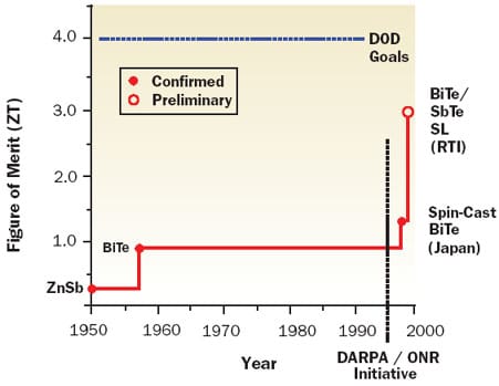 |
Figure 1. History of room temperature thermoelectric figure of merit (ZT) adapted from [1].From the viewpoint of readers of ElectronicsCooling the question to be answered is: How significant might improvements in ZT be for cooling high performance electronic modules? Theoretical expressions can be derived expressing the maximum temperature difference across a thermoelectric or its coefficient of performance (COP) in terms of Z and other pertinent parameters [4,5]. Unfortunately, such is not the case for determining heat pumping capability at a specified cold side or heat source temperature.
Simons presented algebraic solutions for chip temperature (Tc) and allowable module power (Qm) with thermoelectric cooling, taking into account external thermal resistance and coolant temperature [6]. Although the results are dependent upon α, ρ, and k of the thermoelectric materials, the form of the equations reveal that it is not possible to group these parameters together into a single variable, Z. In fact as the subsequent discussion will reveal, it is possible to get different values of Qm for the same value of Z or ZT. From equation 1 it is obvious that there are an infinite number of combinations of α, ρ, and k that will give the same value of Z.
Phelan et al. [7] estimated the possible effect of improved Z by assuming that the improvement is obtained by increasing the Seebeck coefficient while holding ρ and k constant. Simons et al. [8] took this approach a step further considering three cases to achieve a given Z:
1) holding α and ρ constant to find the required value of k
2) holding ρ and k constant to find the required value of α
3) holding α and k constant to find the required value of ρ
For each case the combination of α, ρ, and k was used in the heat pumping equation (8) from reference [6] to determine the maximum module heat load for a given chip temperature. The maximum allowable module power for a given chip temperature was determined by increasing current to the thermoelectric elements until the allowable module power peaked or a hot side temperature of 80°C was reached, whichever came first.
Calculations were performed for a 126 x 126 mm multi-chip module containing thirty 15 x 15 mm chips. All of the chips were assumed to be of equal power. A thermoelectric cooler comprised of four 62 x 62 mm commercial thermoelectric modules was assumed between the top of the module and the base of an air-cooled heat sink. The air inlet temperature was assumed to be 30°C. Further details may be found in reference [8].
The results of calculations for chip temperatures ranging from 0 to 60°C are shown in Figure 2. In all the cases the value of T used in the figure of merit ZT was based upon a room temperature value of 30°C. The line labeled ZT = 0.8 is based upon the values of α (0.0002 Volts/K), ρ (0.001 ohm-cm), and k (0.015 W/cm-K), for present day BiTe thermoelectric elements. The next group of lines for ZT = 2, 3, and 4 is for case 1 and was obtained by holding α and ρ at present day values (i.e., for BiTe) and using the k values needed to give the respective values of Z. The upper-most group of lines for ZT = 2, 3, and 4 is for cases 2 and 3, which gave nearly identical results. Cooling capability without a thermoelectric cooler is shown by the red line in the lower right quadrant of Figure 2 for purposes of comparison.
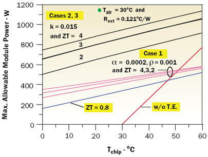 |
Figure 2. Effect of increased thermoelectric ZT on maximum allowable module power.These results show that thermoelectric materials with increased ZT could yield significantly increased module cooling capability. They also clearly demonstrate that materials with the same value of ZT will not necessarily give the same thermoelectric cooling performance. They would also seem to suggest that it is preferable to increase ZT by increasing α or decreasing ρ rather than reducing k.
To further explore the effects of the thermoelectric material parameters on cooling performance, calculations were performed as already described, with α held constant at the present day value (i.e., for BiTe) and ρ and k varied so that ZT = 0.8. Figure 3 shows the results based upon a chip temperature of 40°C.
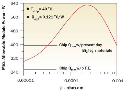 |
Figure 3. Variation in module Qmax with thermal conductivity of TE elements for a Seebeck coefficient = 0.0002 and ZT =0.8.These results show that for a given Seebeck coefficient there is an optimum combination of ρ and k that will maximize thermoelectric cooling performance in terms of heat pumping. For purposes of comparison, the horizontal lines represent the example module cooling capability without any thermoelectric enhancement and with enhancement using present day thermoelectric materials.
These results prompted further calculations to determine what would happen to the maximum module cooling capability at a constant value of ZT for different values of α as ρ and k are varied. Figure 4 demonstrates that for each value of α there is a unique combination of ρ and k that maximizes the allowable value of module power dissipation for a given chip temperature and cooling condition. It may also be seen that the maximum allowable module power is independent of the values of α.
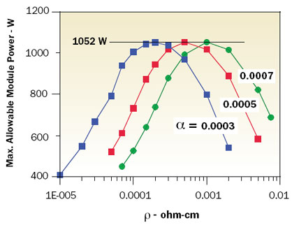 |
Figure 4. Variation in Qmax with thermal conductivity of TE elements for different values of Seebeck coefficient for ZT = 3.0.Based upon this observation, further calculations were performed varying ρ and k with α fixed at 0.0005 for ZT = 2, 3, and 4 to determine the maximum allowable module power for chip temperatures ranging from 0 to 80°C. The outcome of these calculations is shown in Figure 5. The lines for ZT = 2, 3, and 4 are based on optimal combinations of α, ρ, and k to attain the maximum allowable module power. Considering the behavior exhibited by the results shown in Figure 4 (i.e., maximum allowable module power is independent of the value of α at a given ZT), it is expected that the results shown in Figure 5 are at least valid for 0.0003 < α < 0.0007 and probably beyond. Included for comparison are lines of cooling capability for thermoelectric elements with ZT = 0.8 based upon the properties of present day BiTe and for cooling capability without thermoelectric augmentation.
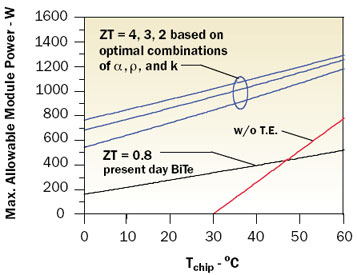 |
Figure 5. Theoretical module power limit for ZTs based upon optimal combination of thermoelectric element electrical resistivity and thermal conductivity.The results presented show that meaningful improvements in module cooling could be obtained with thermoelectrics exhibiting a higher ZT. The reader should also now be aware that materials with the same ZT will not necessarily yield the same cooling performance. The results obtained here using optimum combinations of ρ – k may be considered to represent the theoretical limit for the example module under the specified cooling conditions. Of course the challenge to find or develop new thermoelectric materials that can provide performance approaching the theoretical limits discussed here is one for solid state physicists and material scientists to answer.
References
- Dubois, L.H., “An Introduction to the DARPA Program in Advanced Thermoelectric Materials and Devices,” Proceedings of 18th International Conference on Thermoelectrics,” 1999, pp. 1-4.
- Venkatasubramanian, R., Siivola, E., Colpitts, T., and O’Quinn, B., “Thin-Film Thermoelectric Devices With High Room Temperature Figures of Merit,” Nature, 413, 2001, pp. 597-602.
- Lasance, C.J.M., and Simons, R.E., “Advance in High-Performance Cooling for Electronics,” ElectronicsCooling, Vol. 11, No. 4, November 2005.
- Kraus, A.D., and Bar-Cohen, A., Thermal Analysis and Control of Electronic Equipment, Hemisphere Publishing Corp., New York, 1983.
- Nolas, G.S., Sharp, J., and Goldsmid, H.J., Thermoelectrics: Basic Principles and New Materials Developments, Springer, Heidelberg,Germany, 2001.
- Simons, R.E., “Application of Thermoelectric Coolers for Module Cooling Enhancement,” ElectronicsCooling, Vol. 6, No. 2, May 2000.
- Phelan, P.E., Chiriac, V., and Lee, T-Y, “Current and Future Miniature Refrigeration Cooling Technologies for High Power Microelectronics,” Proceedings of the 17th Semiconductor Thermal Measurement and Management Symposium, 1996, pp. 158-167.
- Simons, R.E., Ellsworth, M.J., and Chu, R.C., “An Assessment of Module Cooling Enhancement With Thermoelectric Coolers,” ASME Journal of Heat Transfer, Vol. 127, January 2005, pp. 76-84.


