Introduction
Recent advances in computer clusters have resulted in the introduction of higher density server equipment that consumes significant amounts of electrical power and produces an extraordinary amount of heat. Due to this latter attribute, which has alarming consequences with regard to thermal management, the installation of modern computer clusters will require well-planned solutions. Interestingly, it has been reported that the industry is rapidly approaching a critical crossroads where performance may need to be sacrificed if air conditioning strategies are pursued, which has been the case for the past ten years or so [1]. It was predicted that a recent and increasingly attractive alternative to mitigate this thermal management challenge will be the implementation of more effective liquid-cooling technologies, which consequently would allow a boost in computational performance, as expected in the fast-paced datacom industry [1].
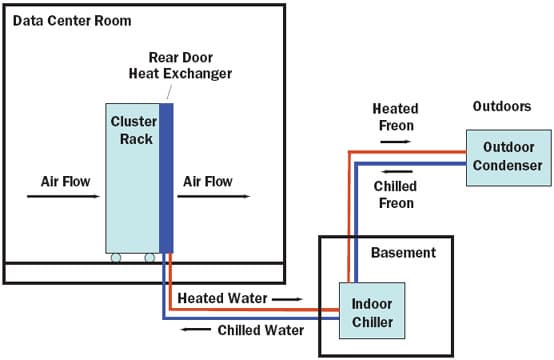
This article describes the installation of a liquid-cooled Linux computer cluster into an existing data center. Due to the strict requirement that the cluster must not perturb other equipment in the data center, special precautions were implemented to properly satisfy this and other environmental constraints. Furthermore, it was necessary to implement a strategy for thermal management that also encompassed future expansion of the cluster(s). As illustrated in Figure 1, the solution was to initially install 30 dual-processor, dual-core blades (120 processors) in a 19-inch EIA-rail rack with a water-cooled heat exchanger mounted to the rear of the rack. Once installed, most of the heat generated by the cluster was efficiently transferred from the air heated by the blades to water flowing through the rear-door heat exchanger. The self-contained, circulating water in this door was directly connected to a small, indoor water chiller, which exchanged the heat to circulating freon gas, which then expelled the heat to an outdoor condenser. This set-up and the implementation of precautionary measures, such as automatic shutdown procedures, are discussed in this article. Overall, the success demonstrated by this well-planned installation should serve as a general example for other data centers, particularly those involving small or medium size installations.
 |
Figure 1. Installation schematic of a liquid-cooled, Linux computer cluster.
Determining Cluster Size, Estimating Heat to be Generated, and Planning for Expansions
Early in this installation, it was important to first define the scope of the project by determining how many and what type of processors would be included in the rack. The impact of this directly influenced the electrical requirements, the quantity of heat produced, and the thermal management strategy. Based on budgetary reasons, it was determined that the rack would initially have 30 dual-processor, dual-core blades, which contained a total of 120 processors.
However, it was also important to plan for the future addition of more blades, along with the resultant electrical and heat consequences. For example, it was estimated that the 30 blade servers, master, and switches would require up to 11.3 KVA of electricity and produce 9.6 KW (32,852 BTU/hr) of heat, and that a full rack of 84 blades would require up to 16.3 KVA of electricity and produce 13.9 KW (47,578 BTU/hr) of heat. Also important to these considerations was that the slower clock speed of the chosen chips produced significantly less heat than those that have higher clock speeds.
Water Cooled Rear-Door Heat Exchanger
Given the above parameters, it quickly became apparent that the conventional approach to expelling the heat produced by a full rack would require the addition of a much larger air conditioner within the data center. However, this would have required significant room modifications and the occupation of valuable and limited floor space. Thus, our thermal management plans were directed toward removing heat more efficiently via liquid cooling and not impacting existing air conditioning infrastructure. Fortunately, several liquid cooling options had very recently become available on the market.
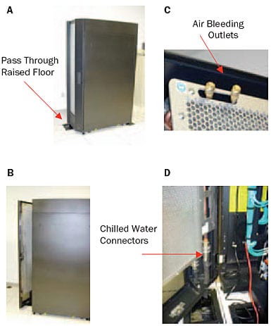
After extensive evaluation of the various configurations and requirements of each option, a rear-door heat exchanger was chosen, due to its simplicity and efficacy [2]. The concept for this solution was straightforward. The rear-door of a typical computer rack was replaced with one that incorporated a fin and tube heat exchanger through which cooled water flowed (Figure 2). The air moving devices within the rack forced the heated air through the rear-door heat exchanger, which extracted a large portion of the total heat load and thus reduced the air temperature being exhausted into the data center.
 |
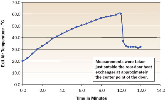
Figure 2. Rear-door heat exchanger [2].Test data acquired on a full rack of 84 blades appear in Figure 3, where temperature measurements at the back of the rack (i.e., after air passed through the heat exchanger) were acquired before and after the introduction of chilled water to the rear-door heat exchanger. The benefit of the door was evident, as there was a rapid temperature reduction from 60 to 32°C at the back of the rack. The door, with its one-pass air path, could effectively extract a large portion of the total heat load (50% to 60% in this case). As a result, there was a significant and sufficient reduction in heat being exhausted into the data center. Any remaining heat was easily managed by an air conditioner, such as those typically found within data centers.
 |
Figure 3. Air temperature versus time for a fully configured blade rack.
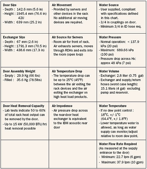
The water flow was started at T0 + 10 min.A more detailed analysis of the design and attributes of the rear-door heat exchanger was of interest. As noted, the door consisted of an aluminum fin and copper tube heat exchanger contained in an aluminum door housing. The housing acted as a plenum to direct air through the exchanger, provided a hinge and latching function, and afforded electro-magnetic interference (EMI) shielding for the rack electronics (Table 1). The air resistance of the door assembly was equivalent to an acoustic-style door. This allowed the server air-flow to be essentially the same as in typical racks, which was important for avoiding any increase in processor temperature. By not requiring additional boost air moving devices, the rear-door heat exchanger design was simplified and reliability improved.
Table 1. Key Attributes of Rear-Door Heat Exchanger [2]
 |
The connection points for the supply/return hoses, which were located on the hinge side of the door to minimize hose movement, were positioned near the low point of the door (Figure 2D). These quick disconnect fittings were double protected and highly reliable. The air bleed valves were located at the high point of the heat exchanger and at the outer edge of the door, angled away from the servers (Figure 2C). These locations minimized exposure to drips or water splash. Likewise, any tubing or manifolds that provided a direct “line of sight” for water spray (in the event of a water leak) were covered for additional server protection.
Inclusion of a heat exchanger into the existing form-factor of a rear rack door also provided a good level of flexibility for data center managers. The rack or system footprint remained approximately the same (rearrangement of racks in a data center layout was not necessary for the initial installation), and the door could be uncoupled, drained, removed from a rack, and moved to a new location within the data center to address “hot spots” with very little time and effort. Flexible hoses, varying in lengths from 3 to 5 meters (10 to 50 ft.), were used for delivering to and returning water from the coolant distribution unit (CDU), and these could also be easily rerouted without disruption or additional cost to the data center infrastructure or functioning server racks.
Dedicated Water Chiller
Another critical aspect of the thermal management strategy was the installation of a water chiller that satisfied multiple criteria. A small, dedicated water chiller [3] was preferred over a building chiller because it allowed a higher degree of user control and maintenance. The rear-door heat exchanger required that a specific temperature of 18°C be employed (unless room dew point monitoring and water temperature controls were used) to avoid water condensation, and it required a minimum water flow of 22.7 LPM.
This was based on ASHRAE’s Equipment Environment Specifications [4]. The chiller, which was selected for this application, monitored room dew point and varied temperature of the conditioned water to maintain the supply water above the room dew point, thus eliminating any chance of condensation (e.g., dry environments can tolerate lower temperature conditioned water due to lower dew points).
Other Precautions and DataCenter Environmental Considerations
Given that the data center already contained mission-critical servers, it was important that overheating of the data center be avoided. Any unplanned shutdowns involving the data center servers could result in company-wide loss of time and productivity. Backup precautions were therefore implemented on the newly installed servers. Since the new servers were not mission-critical, selected blades were set to frequently monitor their surrounding temperature, and an automatic shut-down procedure was set to be initiated if a threshold temperature were exceeded. Such a change in the temperature of the room could arise, for instance, if water no longer flowed through the rear-door heat exchanger of the cluster for an extended period of time due to an unforeseen loss in electricity to the chiller.
New code was written for this temperature monitoring procedure, and it used existing blade monitoring and control capabilities. Specifically, a background temperature-monitoring task ran in two of the nodes (for redundancy) in each blade chassis and periodically checked the reported chassis ambient temperature. Parameter files defined the temperature threshold, the neighboring nodes under control of the monitoring task, and the time between temperature checks. If the temperature exceeded the specified temperature threshold, the monitoring task shut down the other nodes specified in the parameter file and then finally shut down the node in which it was executing.
Other precautions were also implemented, such as secured electrical services. The cluster was connected to an uninterruptible power supply (UPS) electrical line to avoid server interruption. The chiller and the condenser were placed on separate electrical feeders that were backed-up by a generator to avoid electrical failures. Also, the chiller unit was connected to a distal alarm to notify personnel of any malfunction. The chiller reservoir and water lines were filled with deionized water to minimize corrosion over time. Some modifications had to be installed to ensure continual operation under the hot summer and harsh winter conditions found in Montreal,Quebec, Canada. For example, a check valve was installed to prevent non-uniform distribution of the freon gas in the outdoor piping.
Summary and Perspective
In recent years, there has been an impressive growth in the need of computer clusters for a diverse range of commercial and scientific applications. A concurrent trend in the computer industry has been toward building smaller and more compact servers. Thus, cluster racks now house more processors, consume more electricity, and produce much more heat. Given both trends, it has been acknowledged that the industry is at a crossroads, and if innovative strategies for thermal management of clusters are not developed and implemented soon, then the industry will have to sacrifice advances in computer performance.
It must be kept in mind, however, that the ultimate success of any innovative strategy will depend on manufacturers and IT operators. Those IT operators who are not experts in this upcoming thermal management issue will be faced with complex installation decisions. The conventional approach to expelling the heat produced by one or more racks would require the addition of large air conditioning units to the data center, along with major room modifications. Thus, it becomes quickly apparent that the purchase and installation of high-density computer clusters must include careful considerations on how to effectively expel this heat along with a number of peripheral and room-dependent environmental restraints or factors. Consequently, IT operators and manufacturers need to be educated and be capable of assessing the risks.
This article has described the implementation of a water-cooled thermal management solution. It focused on the installation of a specific cluster, and it is hoped that these considerations and decisions can serve as an example and will have utility and applicability to other data centers. However, novel and more practical solutions will certainly need to be sought in the future.
Acknowledgments
The authors would like to thank the following IBM colleagues, G. Massicote, L. Richburg, L. Corriveau, and R. Schmidt. They are also grateful to D. Thériault of Vimoval Inc. for the installation of the water chiller, and to the following BI colleagues, P. Bonneau, T. Blahovici, T. Tucan, E. Bellerive, O. Hucke, A. Jakalian, and J. Gillard.
References
- Schmidt, R., “Liquid Cooling is Back,” ElectronicsCooling, Vol. 11, No. 3, 2005.
- Schmidt, R., Chu, R., Ellsworth, M., Iyengar, M., Porter, D., Kamath, V., and Lehman, B., “Maintaining Datacom Rack Inlet Air Temperatures with Water Cooled Heat Exchanger,” Thermal Management of Electronic and Photonic Systems – Data Center Thermal Management (Proceedings of ASME Summer Heat Transfer Conference & InterPACK ’05, ASME/Pacific Rim Technical Conference and Exhibition), Vol. 2, Paper IPACK2005-73468, San Francisco, California, USA, July 17-22, 2005.
- A dedicated water chiller was purchased from Polyscience, model DCA5o4D1YRR01.
- ASHRAE, “Thermal Guidelines for Data Processing Equipment,” 2004, Equipment Environment Specifications, available from http://tc99.ashraecs.org/


