Introduction
During the last ten years, developments in LED semiconductors have led to an important change in LED applications from that of luminous indicator to that of illuminator. With LEDs now advancing into several lighting fields, LEDs have become one of the standard methods of producing light, joining more traditional sources such as incandescent, fluorescent and high-intensity discharge (HID). Unique to LED lighting, though, is the fact that the source of light is not a filament, gas discharge, or arc, but rather a semiconductor. This is changing the technology associated with the development of lighting, how the lighting will be used, and how the thermal challenges must be resolved. This article addresses the latter issue.
Table 1. Light Source Comparisons [4]
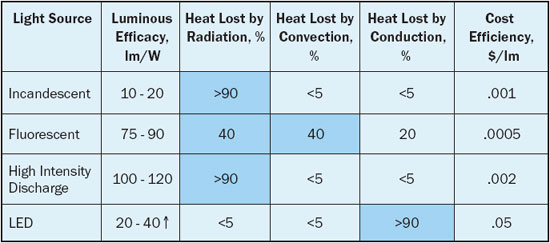
Fluorescent lighting is one of the most common sources in many applications, from large area lighting to smaller bulbs used in LCD backlights. It is the mainstay of most lighting applications today, and offers very good luminous efficacy combined with low cost. Fluorescent is today making greater inroads into fixtures that previously used incandescent lighting now that the compact fluorescent bulbs (CFLs) are priced around US$2 (compared to US$15 for a bulb ten years ago).
Fluorescent technology still has some drawbacks, which makes it vulnerable to replacement in the long term: namely, the use of mercury as the excitement gas (about 5 mg per standard tube), a shorter life than customers would like (20,000 hr MTBF), and poor cold performance. Reduction of Hazardous Substances (RoHS) protocols have grandfathered the mercury in for now, but when a suitable lighting replacement becomes available there will be pressure to move away from fluorescent lighting.
High Intensity Discharge lighting is the most efficient source available. An arc is used to create light and can either produce a range of white light or a single monochromatic source (such as sodium vapor lamps). Typically these lights are used for large area lighting (for example, warehouses or parking lots).
LEDs are still in an emerging stage for light output and cost. During the last decade, they have improved efficacies to above incandescent technology and are now beginning to show luminous efficacies around the lower end of fluorescent lighting. But the industry is observing and predicting that commercially available LED die will exceed fluorescent efficacy in the next three to five years and will end up somewhere around the 150 lm/W mark for white light – far above any current technology.
This situation is causing no small stir in the lighting world, as LEDs are effectively competing in various specialty lighting applications and are now poised to change the general illumination market in the near future. With no RoHS issues, high lm/W efficacies on the horizon, long life (50,000 hrs to ~30% light degradation) and falling costs, the lighting mixture of the future will change dramatically. SolidState Lighting (SSL) is the wave of the future.
The Thermal Paradigm Shift
Shifting light production from filaments, gas discharges and arcs to semiconductors brings about many changes to the lighting field, which has not changed basic technology much in the last 50 years. As seen again in Table 1, conventional lighting sources reject most of the waste energy as infrared heat radiation, and this has led to fixtures and systems optimized for this mode of heat transfer (with convection also applicable to fluorescents). If the reader places his hand in front of one of these sources, there is a considerable feeling of heat on the skin.
However, heat transfer for semiconductors is first a conduction problem, and with LED junction temperatures limited to less than approximately 100°C (in most cases), conduction is the primary transfer method until a suitable area for natural convection is reached. Radiation is small between the die and the system because the LED source is cooler than a filament or an arc. This differentiates LEDs from other lighting sources where most heat is radiated to the environment from non-LED light sources.
Instead of most of the thermal energy leaving the source by radiation, an LED system’s thermal energy leaves via the fixture at a much lower temperature with a mix of primarily natural convection and some radiation. This change in the cooling mechanism for lighting systems cannot be understated, as system designers are not used to thinking and designing for this different thermal system. A suitable path for conducting heat from the LEDs must be provided, and that also includes the various thermal interfaces in the system (often which are just simple sheet metal fixtures with poor contact between parts).
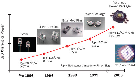 |
Figure 1. LED package changes.
Moving the Heat
LED packages have changed through the last decade to adapt to higher conductive power dissipations. Originally, the 5 mm and 3 mm packages were used as indicators, and these were pressed into service for new die luminaries. However, with 300°C/W for thermal resistances, these packages were not suitable for the increasing powers necessary to meet the light level demand. Figure 1 shows the changes in LED packages during the last decade, with chip on board (COB) devices having the best performance at about 5-10°C/W to the circuit board substrate. Leadframe modifications dominated the early changes until power requirements necessitated the use of a central heat-conducting slug in packages. Figure 2 shows a typical power package design with a central heat slug.
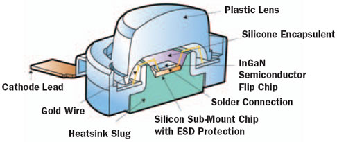 |
Figure 2. Power Package LED Cross Section (courtesy Lumileds).These modifications to the LED packages motivated changes to the circuit boards to handle the increased heat dissipation. With large powers dissipated from the LED leads, and now the central thermal slugs, boards have quickly changed to move this heat appropriately. It is possible to still use standard FR-4 technology boards for LEDs up to 0.5 W dissipation, but above that some metallic substrates are required.
Today it is common to find a metal core printed circuit board (MCPCB), also known as an insulated metal substrate (IMS) board, in use underneath 1W and larger devices. These typically have a 1.6 mm (1/16″) base of aluminum with a dielectric layer attached, followed by copper trace layers and solder masks. The aluminum sheet metal allows the heat to move efficiently away from the LED to the system. Other developments with graphite or copper layers in FR-4 PCBs are under development and may provide alternatives to standard MCPCBs. For extremely high performance applications, ceramic-based systems are available for circuitry.
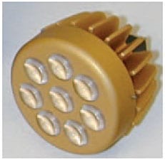 |
Figure 3. Sample LED fixtures.From this point the heat of the LEDs must be removed to the system and dissipated to the ambient. In this area, the system must be adapted to low resistance conductive paths, and most typical fixtures are not adequate. Standard fixtures made with sheet metal do not control interface connections carefully enough for heat transfer, and the area for convection to the ambient may not be enough or in an adequate location. Hence heat sinking fixture designs with proper surface area are required, such as the sample LED system shown in Figure 3. The system cross section is shown in Figure 4. A suitable thermally conductive plastic may also work well for fixtures, and as the thermal conductivity of these plastics approaches 20 W/m-K there is more opportunity to replace metal.
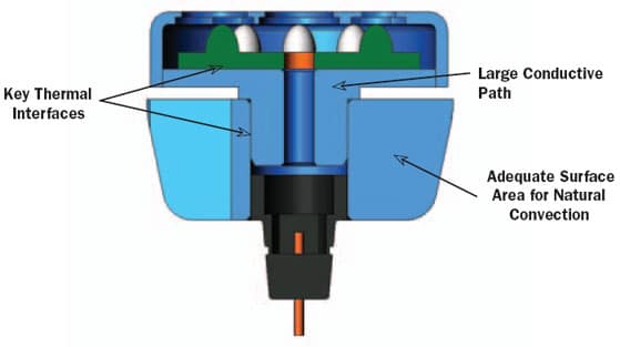 |
Figure 4. Sample LED system cross section.
Getting Active
In more extreme cases of lighting, some type of active cooling may be required. This may be due to high heat fluxes from closely located LEDs, a small volume or surface area that precludes natural convection, or an extremely high ambient temperature condition. Any of these conditions may change the thermal budget in some area and require an active cooling system.
Various “standard methods” for active electronics cooling have been proposed or used for LEDs as well, though some special conditions apply for active LED cooling. To date, systems have used or proposed using simple DC rotary fans, thermoelectric coolers (TECs), piezoelectric fans (PZFs), synthetic jets (SJs) and liquid cooling (such as microchannels). Each of these has particular advantages, but also carries some disadvantages for cooling a lighting system.
Active cooling for lighting has a few special requirements that are not necessarily required for every semiconductor application. For example, most lighting systems must not produce objectionable noise levels. This implies any active cooling system must be quiet, and moving active systems can generate objectionable noise unless precautions are used.
Other considerations for active light cooling systems are:
- Lifetime – Typically 50,000 hours for the LED product
- Low power consumption – An issue for TECs as efforts are ongoing to improve energy and further enhance Energy STAR [3] ratings for LED lights
- Low susceptibility to dust/foreign contamination – An issue for systems with moving parts and air streams
- Ability to tolerate cyclic loading – An issue since lights are frequently turned on and off
- System cost addition – An issue today for liquid loop systems, such as microchannels
With all these issues, is there any reason at all to consider active cooling? The answer is yes, given how LEDs can supply light. Many LEDs can increase light output with additional current input, until the point of current saturation. Today, the most costly parts of an LED system are the LEDs themselves. If one can reduce the LED count by driving the LEDs with higher currents, then the system cost can be sharply reduced. Adding cost with an active cooling system can actually reduce the overall system cost by lowering the LED count. Hence a good active cooling system is an advantage, when it is designed properly, which means it must be efficient, quiet, reliable, and cost effective.
Summary
LEDs are changing the world of lighting due to their efficiencies, size, durability, and lifetime cost. One of the key changes in lighting system design is adapting to a primarily conduction-based heat transfer design within the system, followed with an adequate convection design to the ambient air. This will require new designs of the LED system and the lighting fixture designs that will act differently than previous generations of lighting where radiation played a dominant role. The challenges to develop new systems of passive and active cooling will keep LED and lighting designers busy for the foreseeable future.
Footnotes
- Readers should note that the lighting industry often uses the word efficiency in place of efficacy though the usage is not technically correct. Efficacy is a measurement of the system lumens per watt of energy consumed; efficiency is the efficacy divided by the maximum 683 lumens per watt of a 555 nm source. Most industry information typically incorrectly reports efficiencies in lm/W. This confusion is pervasive in most literature and product specifications.
- Lumens per Watt, in normal SI abbreviation, are lm/W; however, the lighting industry has chosen to use the abbreviations LPW or lpw to indicate this in most literature, including light bulb packages in retail stores.
- Further information about ENERGY STAR ratings can be found at the US government website http://www.energystar.gov/.
- Data for current light sources from GE Lighting (internal documents).


