High performance thermal interface materials (TIMs) inserted between the CPU lid and heatsink – generally referred to as the “TIM2” – provide a reworkable low resistance thermal path in the package stack-up. It is well-recognized that users need to monitor the thermal performance of the TIMs to verify vendor data [1, 2]. Less well-known is that the TIM2 can also mechanically couple the two surfaces through a weak adhesive bond [3]. As cooling of high performance systems drive adoption of higher performance thermal materials, it is worth noting that the same properties of TIM2s that reduce interfacial contact resistance between surfaces tend to increase the mechanical bonding strength between these interfaces. Combined with the increasing weight and height of high performance air cooled heatsinks, this dynamic loading must be considered in the design of heat sink interface, interconnect, and package retention mechanisms.
For example, if the adhesive forces exceed the retention force of the micro pin grid array (μPGA) interface or land grid array (LGA) socket interfaces, then under certain dynamic loading conditions – such as dynamic shock impulses experienced during shipping or tensile forces exerted during manual heatsink removal – damage may occur. This applies, in particular, to lidded CPU applications, where the increasing contact area of lid and heatsink significantly increases the adhesion force at the interface. Data on the adhesive bonding properties of non-curing TIM2s, unlike strongly bonded adhesives or solder, are not reported on vendor data sheets nor in the literature. This data, however, is needed to predict how the TIM interface will behave when the system is subject to tensile forces during manual separation or dynamic loading induced by shock impulses.
As detailed in [3], a series of controlled tests based on ASTM standards for adhesive materials [4], have been designed and implemented to measure the tensile pull strength of the TIM adhesive bond. TIM2 materials were inserted between two machined Al-blocks having a 25 x 25 mm contact area, a surface roughness of nominally 0.7 μm, and a surface flatness between 10 and 20 μm. Typical test joints had a bondline thickness of 20-50 μm. Specimen joints were tested at t(0) to failure on a universal testing machine, using a separation velocity of 0.02 mm/sec.Mechanical bond strengths of a number of candidate TIM2 materials – representative of the major commercial TIM categories, thermal greases, phase-change materials (PCMs), puttylike materials, and dry films – were measured in this survey.
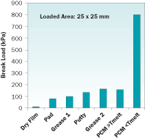
Break loads for the materials tested are presented in Figure 1. As shown in this chart, the tensile break loads ranged from 80 kPa for a gap filler, to 200 kPa for greases and PCMs above the phase change temperature, to 800 kPa for a solidified PCM. While the tensile loading represents an upper limit for these materials at the relatively slow loading rate used, the force could be larger under dynamic loading conditions with higher loading rates. Actual loading on sinks and packages would have combined shear and peeling stresses, which would tend to reduce breaking loads at the same loading rate. If reworking a package or removing a sink in a confined space, the tensile case reported here would be approached and the data could be used directly. Note that for the solidified PCM, a force of over 510 N (115 lbf) was required for separation in these tests.
Dynamic loading arising from this adhesive force can manifest itself in practice when the sink attach hardware from a lower performance sink design is transferred to a higher performance sink, without adequate consideration of the increased sink size and weight. A case in point involves volume PC manufacturing transitioning into the server space with outsourced design. Here, shipping and handling loads can cause damage to the package and/or interconnect when tensile forces are present in the TIM layer. Further, as air-cooled heatsink performance is pushed to higher limits, the very tall fin structures employed require that careful dynamic loading considerations be applied to the sink attachment schemes. Traditional spring-mounting at the sink base, for example, cannot be made stiff enough to avoid sink sway without introducing potential load magnitude and load tolerance issues for the device and interconnect being used.
This Technical Brief illustrates how adhesive bonding at TIM2 interfaces can represent significant loading to the package and interconnects. Increased mechanical coupling between the package lid and heatsink and the magnitude of this bond strength must be considered in the mechanical design. While thermal performance is the ultimate driver in the choice of TIM for a particular application, ease of use and field reworkability are also important considerations. This methodology for characterizing the adhesive properties of TIM interfaces could be readily adapted by others in the industry, including the supplier base.
Acknowledgments
The authors would like to thank Sun Systems Group for supporting this work and their colleagues for helpful insights.
References
- Wilson. J. And Guenin, B, “Cooling Solutions in the Past Decade,” ElectronicsCooling, Vol. 11, No. 4, Nov. 2005.
- Stern, M. B., Gektin, V., Pecavar, S., Kearns, D., and Chen, T., “Evaluation of High Performance Thermal Greases for CPU Package Cooling Applications,” Proceedings, Semi-Therm 21, March, 2005, San Jose, CA, pp. 39-43.
- Stern, M.B., Jhoty, G., Kearns, D., and Ong, B., “Measurements of Mechanical Coupling of Non-curing High Performance Thermal Interface Materials,” Proceedings, Semi-Therm 22, March 2006, Dallas, TX, pp. 37-41.
- ASTM D 2095, “Standard Test Method for Tensile Strength of Adhesives by Means of Bar and Rod Specimens,” West Conshohocken, PA, http://www.astm.org.


