Introduction
Today, there is a specific demand by the electronics consumer market: more devices using low power processors with multiple simultaneous CPU functions. Due to the significant demand in computing needs, the International Technology Roadmap for Semiconductors (ITRS) 2005 predicts an increase in the overall power consumption for some platforms [1]. The cooling issues for these emerging devices may be more complex and significantly different from the traditional large form factor devices such as desktop and servers. For example, these markets may require lower cost, lower power consumption, and lower noise cooling devices compared to what we have today. Using the current knowledge from the mobile markets, the heat spreading contribution to the total thermal resistance can be well predicted. Usually, the thermal resistances associated with spreading are significantly smaller compared to the convective air side resistance. Thus, for better return on investments, the cooling research focus should be on improving the air forced convection. Small rotational fans or small blowers are often used to increase the bulk fluid motion; however, the space, cost, power and noise of these fans may not be feasible for some of these applications. This article will focus on piezo fan technology, which presents multiple advantages over conventional fan technologies, especially in cooling low power processors. Some of the work may be applicable to synthetic jets too since they also use piezo actuators. This paper is also a call to the piezo industry to deploy more capability for piezo fans used in the electronics cooling of future low power processors.
Technology Description
Although the first experimental demonstrations of piezoelectric phenomena were published in the early 1880s [2-3], its application for air flow generation started much later [4] and recently more piezo related work was done specifically for the electronics cooling market [5-8]. The “inverse effect” of the piezoelectric phenomena, where stress is generated as a response to an applied electric field, is the basis for development of a new generation of piezo fans.
Figure 1. Air flow generation using piezo actuators.
| Parameters | Description |
| Input Voltage | 115VAC, 60 Hz |
| Capacitance | 15 nF |
| Power Consumption | 30 mW |
| Weight | 2.8 grams |
| Size | 75 mm L x 12.5 mm W |
| Blade Swing | 25.4 mm |
Figure 1 shows a particular application where the “inverse piezo effect” is used to generate air flow. It can be seen that a long metal or plastic blade is bonded to a piezoelectric material in a cantilever fashion. If an electric field is applied to a piezo layer the randomly oriented ions go into alignment, which will cause deformation of the piezo layer. Under an alternating current the blade vibrates back and forth with the same frequency as the alternating current. This vibration generates air flow, which in turn may improve cooling of some electronic components.
Increasing the amplitude of the piezo actuator is desirable since the larger the amplitude is, the greater the air flow will be. It has been shown that the maximum amplitude occurs at a single frequency, which is the resonance frequency of the assembly between piezo and the blade [7]. In most, if not all cases, the relationship between amplitude and frequency is highly nonlinear, and greater voltage produces larger amplitudes [7].
Conventional Piezo Fan and Heat Sink
In Figure 1 it can be seen that the piezo fans are placed in front of a heat sink (operating in phase). The piezo vibrates in the vertical plane and a duct with no bypass has been used. The aluminum heat sink has seven fins 1 mm thick with the overall dimensions as shown in Figure 1. The heat sink was attached to a bare die (size : 1 x 1cm). The piezo actuator dimensions are presented in Table 1. For the natural convection tests, the duct was removed and the piezo actuators were not powered.
The sink to ambient resistance is defined as:
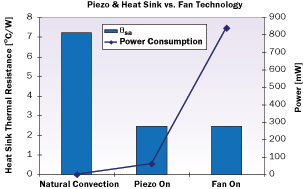
Figure 2. Conventional piezo and heat sink performance.
Where Ts (°C) is the sink temperature measured in the middle of the heat sink base, Ta (°C) is the ambient room temperature and QCPU (W) is the power dissipated by the processor.
Figure 2 shows the heat sink thermal resistance test results for this heat sink and piezo combination (on and off situation). The performance of the piezo fan was compared with a particular existing axial 25 x 10 mm fan (NMB 1204KL-04W-B40), which could fit into the geometrical specifications. It can be seen that the piezo significantly reduces the thermal resistance compared to natural convection, and with an order of magnitude lower power consumption compared to the axial fan.
There are two other major advantages for the piezo fans: noise and cost reduction. As per [7] the noise frequency for the applications considered is significantly below 100 Hz, thus could be inaudible. Using Kuchina’s information on piezo buzzers [9] it can be said that the cost of the piezo could be significantly lower than the current axial fans costs.
Piezo and Boundary Layer Effects
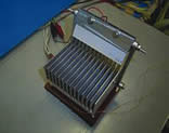
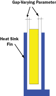
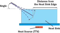
The destruction or “thinning” of the boundary layer is one of the major objectives for air cooling improvements. This section recommends a particular arrangement of piezo blades, which ensures that air flow is generated and at the same time the thermal boundary layer is disturbed by the proximity of the blade. Figure 3(a) shows many piezo blades interwoven between the heat-sink fins very close to the surface of the fins. Figure 3(b) and 3(c) shows the main varying parameters used during testing: the inclination angle with respect to horizontal, the inserted length into the heat sink and the gap between the blade and the heat sink fins. These tests were performed to find the best position and the impinging angle for maximum enhancement of the convection performance.
The heat sink geometry was as follows: height (H) = 38.1 mm, length (L) = 88.9 mm, width (W) = 76.2 mm, fin gap = 6.1 mm, fin thickness = 0.91 mm and base thickness = 6.1 mm.
 a |
 c |
 b |
Figure 3. (a) Photo-Multiple piezo blades and heat sink assembly (Patent Pending); (b) and (c) main varying parameters.
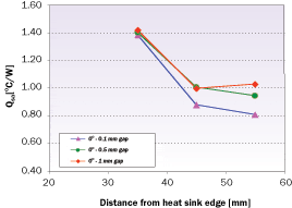 Figure 4a. Piezo and boundary layer effects at different gaps. |
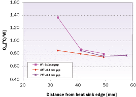 Figure 4b. Piezo and boundary layer effects at different angles. |
Figure 4(a) shows the sink to ambient performance (as defined in Equation 1) as a function of the gap between the blade and fin. For these tests, the gap between the blade and the heat sink fin has been decreased from 1 mm to 0.1 mm and the piezo patch was initially at horizontal. As expected, the 0.1 mm gap improved the cooling performance due to the fact that it better disturbs the thermal boundary layer and that the larger width blade generates more air flow. Also, it can be seen that once the blade is gradually withdrawn from the heat sink (increased distance from the edge) the inclination angle has no significant impact on thermal performance. This is expected as more fin area will be exposed to air flow. For the tests described in Figure 4(b) the gap between the blade and fins was kept constant at 0.1 mm for all tests and the angle was varied. It can be seen that once the blade is withdrawn from the heat sink at an optimum position, the inclination angle has no significant impact on the thermal performance. This can be explained by the fact that the thermal boundary layer near the fin is destroyed in a comparable fashion in all cases and that the air flow generated may not be a function of the chosen orientations. Three dimensional CFD modeling is in progress to further explain this issue.
Challenges for the Piezo Industry
One of the main technical challenges for enabling the piezoelectric technology in the electronics products is the high operating voltage (> 100 V) required to drive the conventional piezos. However, the voltage can be significantly reduced by implementing the so called “multiple layers” piezoelectric fan concept. The multiple piezoelectric layers are connected electrically in parallel. Fundamentally it is possible to reduce the voltage for the same amplitude proportionally with the number of layers; however, manufacturing issues (i.e., thickness of the electrode) may be limiting this voltage reduction. The multilayer technology may also be used to reduce the length of the piezoelectric actuator and get the same amplitude as a longer one.
Although the multilayer piezo technology is used in other applications [10-11], it is not yet applied to electronics cooling due to some key material science issues, yield and reliability, which are not specifically addressed. Some preliminary data, based on accelerated tests using voltage and frequency as variable parameters, show no potential show stoppers [12], but more data needs to be collected for all other reliability requirements. It is hoped that the piezo industry may form interdisciplinary teams of materials, thermal and mechanical engineers to focus on the above issues.
Conclusions
This article has shown that in some applications piezo actuators combined with heat sinks may offer significant cooling improvements. Conventional piezo heat sink arrangements show significant reduction in thermal resistance compared to natural convection. When blades are inserted between the heat sink fins the thermal resistance can be further reduced due to thinning of the boundary layer. This article is also a call to the piezo industry to deploy more capability for the piezo fans used in the electronics cooling of low power processors. The piezo industry should consider the array of challenges mentioned above to make this technology feasible for high volume manufacturing.
Acknowledgments
I would like to acknowledge the following people for their advice and support: Masataka Mochizuki (Fujikura Ltd.), Greg Chrysler, Hakan Erturk, Ward Scott, Cheng-chen Hsieh, Chia-Pin Chiu and Ravi Mahajan.
References
- International Technology Roadmap for Semiconductors, 2005 Edition (http://www.itrs.net/Links/2005ITRS/Home2005.htm)
- Curie, J., and Curie, P., “Development by Pressure of Polar Electricity in Hemihedral Crystals with Inclined faces,” Bulletin Soc. Min de France, 3, 1880, pp. 90-93.
- Lippmann, G., “On the Principle of Energy Conservation,” Ann. Chem. and Phys, 24, 1881, pp. 145-178.
- Toda, M., “Theory of Air Flow Generation by a Resonant Type PVF2 Bimorph Cantilever Vibrator,” Ferroelectrics, Vol. 22, 1979, pp. 911-918.
- Aç›kal›n, T., Wait, S.M, Garimella, V.S., and Raman, A., “Experimental Investigation of the Thermal Performance of Piezoelectric Fans,” Heat Transfer Engineering, Vol. 25, 2004, pp. 4-14.
- Aç›kal›n, T., Sauciuc, I., and Garimella, V.S., “Piezoelectric Actuators for Low Form Factor Electronics Cooling,” Proceedings of IPACK2005-ASME InterPACK, San Francisco, CA, July 17-22, 2005.
- Sauciuc, I., Moon, S.W., Prstic, S., Chiu, C.P., Chrysler, G., “Key Challenges for the Piezo Technology with Application to Low Form Factor Thermal Solutions,” Proceedings of ITHERM2006, San Diego, CA, 2006.
- Sauciuc, I. ,“Investigating Electronics Cooling Technologies”, Advance Packaging Magazine, December 2005.
- Uchino, K., “Piezoelectric Ultrasonic Motors: Overview,” Smart Mater. Struct. 7, UK, 1998, pp. 273-285.
- Andersen, B., Ringgaard, E., Bove, T., Abareda, A., and Pérez, R., “Performance of Piezoelectric Ceramic Multilayer Components Based on Hard and Soft PZT,” Proc. of Actuator 2000, Messe, Bremen, Germany, 2000, pp. 419-422.
- Randall, C.A., Kelnberger, A., Yang, G.Y., Eitel R.E., and Shrout, T.R., “High Strain Piezoelectric Multilayer Actuators – A Material Science and Engineering Challenge”, Journal of Electroceramics, 14, 2005, pp. 177-191.
- Sauciuc, I., Hood, C., “Cooling Solutions for Non-Conventional Applications,” Intel Developer Forum – Fall 2006, San Francisco, CA, September 2006.


