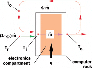
 Figure 1. Schematic diagram of simple computer rack air recirculation model. |
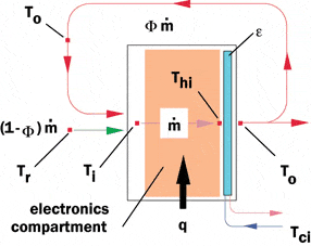 Figure 2. Schematic diagram of computer rack air recirculation model with heat exchanger in rear of computer rack. |
In an article in the November 2006 issue of ElectronicsCooling it was noted that “advances in computer clusters have resulted in the introduction of higher density server equipment that consumes significant amounts of electrical power and produces an extraordinary amount of heat” [1]. Such advances are taxing the ability of many data centers to provide sufficient air conditioning capacity to handle the associated heat loads. The same article and an earlier one [2] discussed the use of air-to-water heat exchangers at the rear of high power computer racks to cool the hot air exiting these racks. This approach helps to reduce the demand on computer room air cooling (CRAC) units and to alleviate “hot spot” problems associated with recirculation of hot exhaust air [3]. This Calculation Corner article will illustrate how a simple air recirculation model may be used to explore the relative effectiveness of this approach.
Air Recirculation Model (without Heat Exchanger)
We will first consider air recirculation without a heat exchanger in place. To do this, consider the schematic of the simple model illustrated in Figure 1. In this model air flows through the computer rack with a mass flow rate, m , entering the rack at temperature Ti and exiting at temperature To due to the heat load, q, within the rack or as given by the following equation,
[1]
A fraction, Φ, of the air exiting the rack recirculates and mixes with the cool room air at temperature, Tr, supplied by the CRAC units. It is assumed that the recirculating air flow rate, Φm , and cool room air flow rate, (1-Φ)m , fully mix to satisfy equation [2],
[2]
Combining equations [1] and [2] it is found that the temperature of the air entering the electronics compartment is given by,
[3]
The temperature of the heated air leaving the rack is given by,
[4]
Air Recirculation Model (with Rear Heat Exchanger)
Next, we will consider the same air recirculation model, but with a water-cooled air-to-liquid heat exchanger in the rear of the computer rack as shown in Figure 2. It is assumed that the heat exchanger has an effectiveness, ε, and is cooled with water at temperature, Tci. In this case air enters the electronics compartment at temperature Ti, and then enters the heat exchanger at temperature Thi, as given by equation [5],
[5]
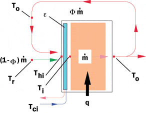 Figure 3. Schematic diagram of computer rack air recirculation model with heat exchanger at front of computer rack. |
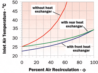 Figure 4. Effect of air recirculation on electronics compartment air inlet temperature with and without water-cooled heat exchanger. |
The quantity of heat, qhtx, extracted from the air by the heat exchanger is given by
[6]
and
[7]
where Cmin in equation [6] is the smaller of the air or water heat capacity rates (m cp) and m cp in equation [7] is the air heat capacity rate. Using equations [2], [5], [6], and [7], after a bit of algebraic manipulation we can arrive at the equation for the temperature of the air entering the electronics compartment, which is,
[8]
Air Recirculation Model (With Front Heat Exchanger)
Last, we again consider the same air recirculation model, but, now with a water-cooled air-to-liquid heat exchanger in the front of the computer rack as shown in Figure 3. In this case, the recirculating air at temperature To, and the fresh room air at temperature Tr, mix to enter the heat exchanger at temperature Thi, as given by,
[9]
The quantity of heat, qhtx, extracted from the air by the heat exchanger is given by equation [6] and also by,
[10]
The temperature, To, of the air exiting the computer rack is again determined by equation [1]. Using equations [1], [6], [9], and [10], and again after a bit of algebraic manipulation we can arrive at the equation for the temperature of the air entering the electronics compartment, which in this case is,
[11]
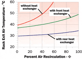 Figure 5. Effect of air recirculation on computer rack exit air temperature with and without water-cooled heat exchanger. |
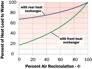 Figure 6. Effect of air recirculation on percent of total heat load rejected to water. |
Example Results
Now, to illustrate the utility of the simple recirculation model and the resulting equations with and without a water-cooled heat exchanger, we will consider the following representative values of the relevant quantities:
- Rack heat load (q) – 20 kW
- Rack air flow rate (m) – 1.37 kg/s (2500 CFM)
- Room air temperature – 25°C
- Water flow rate – 0.94 kg/s (15 gpm)
- Water inlet temperature (Tci) – 20°C
- Heat exchanger effectiveness (ε) – 0.5
Using the above values and the equations discussed in this article the inlet air temperature to the electronics compartment was calculated for air recirculation values ranging from 0 to 100%. As shown in Figure 4 without the water-cooled heat exchanger, inlet air temperature increases dramatically as air recirculation increases. Of course this rise in cooling air temperature will be directly reflected in increased component temperatures. With the water-cooled heat exchanger in place (rear or front) air temperatures entering the rack are well controlled. It may be noted that in this case for values of recirculation below 35%, the heat exchanger in the front actually cools incoming air below the room air temperature. It may also be noted that at 100% recirculation whether the heat exchanger is in the front or back gives the same result. The results for 100% air recirculation are the same as would result for closed-loop air cooling with a water-cooled heat exchanger within the rack.
Figure 5 illustrates the results obtained in terms of the exit air temperature from the rack. Again, as might be expected the exhaust air temperature rises significantly with increasing air recirculation. It may also be noted that the exit air temperature is under much better control with the heat exchanger in the rear of the rack rather than the front of the rack. This is because the heat exchanger in this position “sees” warmer air than a heat exchanger in the front of the rack. As is shown by equation [6], the amount of heat extracted by the heat exchanger is directly proportional to the difference between the temperature of the “hot” fluid (i.e., air) entering the heat exchanger and the temperature of the “cold” fluid (i.e., water) entering the heat exchanger. This is clearly demonstrated in Figure 6, which shows the percent of the total heat load rejected to water depending upon whether the heat exchanger is in the rear or front of the rack. These results show that the heat exchanger in the rear is much more effective in reducing the heat load to room air than a heat exchanger in the front of the rack.
It is hoped that this article has not only demonstrated the effectiveness of using a water-cooled heat exchanger to reduce the heat load to room air; but, has also demonstrated how effective even a simple model can be in providing meaningful results.
References
- LaPlante, S.R., Aubry, N., Rosa, L., Levesque, P., Abroumrad, B., Porter, D., Cavanaugh, C., and Johnston, J.,“Liquid Cooling of a High-Density Computer Cluster,” ElectronicsCooling, Vol. 12, No. 4, November 2006.
- Schmidt, R., “Liquid Cooling is Back,” ElectronicsCooling, Vol. 11, No. 3, August 2005.
- Schmidt, R., “Hot Spots in Data Centers,” ElectronicsCooling, Vol. 9, No. 3, August 2005.


