 |
 |
|
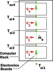
Figure 1. Four board high rack with
serial air flow configuration. |
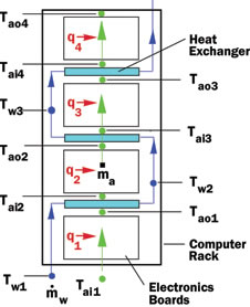
Figure 2. Rack with intercoolers cooled by water flowing parallel to air flow direction.
|
In the February 2007 issue of ElectronicsCooling the Calculation Corner article addressed the use of a water-cooled air-to-liquid heat exchanger to reduce computer rack air exhaust temperatures and mitigate the effect of air recirculation on rack air inlet temperatures [1]. In this issue the Calculation Corner addresses another example of the use of water-cooled air-to-liquid heat exchangers to augment air-cooling. In this case the heat exchangers are used as intercoolers between successive boards of electronics in a serial air flow configuration. The equations required to determine air temperatures throughout the rack without and with intercoolers will be discussed. Example calculations will be presented to compare the effect of intercoolers in a rack with a completely air-cooled rack. A rack configuration comprised of a vertical stack of four electronic boards cooled by a serial air flow (as shown in Figure 1) will be used as a basis for comparison. In this configuration, the air heated by and exiting from one board constitutes the inlet cooling air to the next board in the stack. The same serial air flow rack configurations with water-cooled intercooler heat exchangers are shown in Figures 2 and 3. Heated air exits one board and flows through an intercooler before entering the next board. Provided that the water flowing through the intercooler is cooler than the air, some of the heat being carried by the air will be transferred to the water resulting in cooler air entering the next board. As shown in Figures 2 and 3, water may be supplied to the intercoolers by flowing in a direction parallel or counter to the direction of air flow through the rack.
Air Temperatures without Intercoolers
We will first direct our attention to calculating the air temperatures in a rack without intercoolers. To do this it is necessary to specify the air inlet temperature, Tai1, to the first board and then calculate the temperature rise in the air as it flows across each electronics board. The temperature rise, DTa-b, in the air flow across any electronics board in the stack is given by,
|
|
(1)
|
where qbn is the total heat dissipation of all the components on the board and Ca is the heat capacity rate of air. The heat capacity rate of air is the product of the mass flow rate of air, a , and its specific heat at constant pressure, cpa. The air temperature, Taon, exiting any board in the stack is given by
 |
(2)
|
where the subscripts n and n+1 denote position in the stack. Of course the temperature, Taon, of the air exiting a board, is equal to the temperature, Tain+1, of the air entering the next board in the stack. For this case, calculating the air temperatures throughout the rack is simply a matter of moving up the stack board by board applying equations (1) and (2).
Air Temperatures with Intercoolers (Parallel Flow)
We next turn our attention to calculating the air temperatures in a rack with intercoolers. The water flow to each intercooler is assumed to be in a direction parallel to the air flow through the rack as shown in Figure 2. The calculation sequence required is similar to that in the preceding case except that the temperature change in the air as it flows through each intercooler must be taken into account. To do this it is necessary to calculate the quantity of heat, qw, transferred from the air stream to the water as it passes through each intercooler. This is given by,
|
|
(3)
|
where e is the heat exchanger effectiveness and Cmin is the smaller of the air or water heat capacity rates. As with air, the heat capacity rate of water is the product of the mass flow rate of water, 
|
|
(4)
|
The minus sign in equation (4) indicates that heat is transferred from the air to water. In the event that the inlet water temperature exceeds the inlet air temperature this sign becomes positive indicating that heat is transferred from the water to the air, which, of course, would be undesirable. The temperature of the air exiting the intercooler and entering the next board is then given by,
 |
(5)
|
Of course, as the water passes through an intercooler, its temperature will rise before entering the next intercooler. So it is necessary to calculate the temperature rise in the water as it passes through each intercooler. This is given by,
|
|
(6)
|
The temperature of the water exiting one intercooler and entering the next board is then given by,
 |
(7)
|
Determining the air temperatures throughout the rack is simply a matter of following the air flow and water flow through the rack and applying the preceding equations step-by-step. Starting with the specified air inlet temperature, equations (1) and (2) are used to determine the air temperature exiting the first board and entering the first intercooler. Equation (3) is then used to determine how much heat is removed from the air passing through the first intercooler. Equation (5) is then used to determine the temperature of the air exiting the first intercooler and entering the second board. Equations (6) and (7) are used to determine the temperature change in water passing through an intercooler and the temperature of water entering the next intercooler. This process is then repeated for each board and intercooler.
Air Temperatures with Intercoolers (Counterflow)
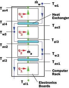
We now turn our attention to the configuration shown in Figure 3, with the direction of water flow supplied to the intercoolers counter to that of the air flow direction through the rack. This situation is a bit more complicated than with the parallel flow case. For the parallel flow case we specified the water temperature into the first intercooler and were able to move up the rack calculating air and water temperatures step-by-step up the rack. For this case the specified water temperature is that entering the top intercooler and the water temperature increases as it moves down the rack through each intercooler.
Figure 3. Rack with intercoolers cooled by water flowing counter to air flow direction.
At this point it is not possible to determine how much heat is extracted by each intercooler because the air temperatures entering the intercoolers are still unknown. However, by adopting an iterative approach we can still start at the bottom and move up the rack stepby-step as was done for the parallel flow case. If we assume how much heat is extracted from the air by the second and third intercoolers, we can proceed to calculate the temperatures throughout the system as before. Doing this we can also obtain a revised estimate of the heat extracted by the second and third heat exchangers, which can then be used as the starting point for the next iteration. The process may be repeated until all the variables stop changing and the final solution is obtained. This process is illustrated in detail in Table 1 with example results.
Example Results
To illustrate the effect of intercoolers and the application of the preceding equations, calculations were performed for each of the three configurations: a) without intercoolers; b) intercoolers with parallel water supply; and c) intercoolers with counterflow water supply. The calculations were performed with the following representative values of the relevant quantities:
|
6 kW (1.5 kW/board) |
|
0.164 kg/s (300 CFM) |
|
30°C |
|
0.126 kg/s (2 gpm) |
|
20°C |
|
0.55 |
The results are tabulated in Table 1.
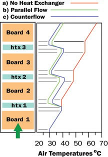
The two left hand columns in Table 1 give the sequence of calculations and complete equations for the counterflow intercooler analysis. The six intermediate columns give the results for each iteration of the counterflow intercooler analysis. An initial guess of 0 was entered for the estimated heat extracted from the air by the second and third intercoolers. As may be seen in the table a final solution was obtained in six iterations. The author found that even less iterations were required if the total heat load of the second and third boards respectively were used for the initial estimates of the heat extracted from the air by the intercoolers. The two right hand columns in the table provide comparable values of the variables in each row calculated for the parallel water flow case and the case without intercoolers. Air temperatures throughout the rack are shown graphically in Figure 4 for each of the three cases considered. As may be seen the intercoolers dramatically reduced air temperatures in the rack after the first board.
Figure 4. Air temperatures throughout rack:a) without intercoolers;
b) intercoolers with counterflow water supply; and c) intercoolers with parallel water supply.
This would of course mean that component temperatures would decrease accordingly with the use of intercoolers. The exit air temperatures were dropped by 27.9°C and 25.5°C respectively, for intercoolers in the counterflow and parallel flow configurations compared to the conventional air cooling configuration. In addition 77% and 70% of the total heat load was carried away by the water flowing though the intercoolers in the counterflow and parallel flow configurations respectively, thus reducing the heat load on the room air conditioning. These results clearly demonstrate the effectiveness of using water-cooled intercoolers to manage air temperatures in an aircooled rack. This is further attested to by the fact that for many years a major computer manufacturer used this technique to cool large mainframe computers [2].
References
- Simons, R.E., “Using a Simple Recirculation Model to Explore Computer Rack Cooling,” ElectronicsCooling, Vol. 13, No. 1, February 2007.
- Chu, R.C., Simons, R.E., Ellsworth, M.J., Schmidt, R.R., and Cozzolino, V., “Review of Cooling Technologies for Computer Products,” IEEE Trans. on Device and Materials Reliability, Vol. 4, No. 4, December 2004.


